33
Installation instructions
ENGLISH
CH
C
P.
CH
P. Car.
DHW
Stemp.
ACC
Y4
1
2
3
4
1
2
3
1
2
3
4
5
6
Y3
Y2
12 11 10 98 765
4321
0
1
2
3
4
5
6
7
8
9
981011121314
2134567
Jp2
L
Y4
1
2
3
4
1
2
3
1
2
3
4
5
6
Y3
Y2
12 11 10 98 765
4321
0
1
2
3
4
5
6
7
8
9
981011121314
2134567
Jp2
SE
24 V -DC
CM 140 - cascade manager
24 V -DC
BR
BK
R
S
M
G
FL
D
230 V - 50 Hz
L1
PE
N
2
L1
PE
N
1
C C CNC NC NO
1.3 (T.S.)
1.2 (P. min.)1.1 (P. max.)
SAFE
1
NPEL1
Menu
L
N
SS
M
Ext. MinDPIn
0-10V
P.
mod.
D
230 V - 50 Hz
L1
PE
N
2
L1
PE
N
1
NPEL1
Menu
+ 24 V
(-)
eBUS +
1
2
3
4
1
2
3
4
5
6
7
Menu
678910 11 12 FL TA
INAIL
Y2-BCM
12345
1
Y3- BCM
Y2-HSCP/UFLY
56
843
Y1-BMM1
4321
Y4- BCM
23
eBUS -
eBUS +
FL
1
C C CNC NC NO
1.3 (T.S.)
1.2 (P. min.)1.1 (P. max.)
SAFE
L
N
SS
M
Ext. MinDPIn
0-10V
P.
mod.
678910 11 12 FL TA
INAIL
Y2- BCM
12345
1
Y3- BCM
Y2-HSCP/UFLY
56
843
Y1-BMM1
4321
Y4- BCM
23
eBUS -
eBUS +
B
B
0
1
2
3
4
5
6
7
8
9
0
1
2
3
4
5
6
7
8
9
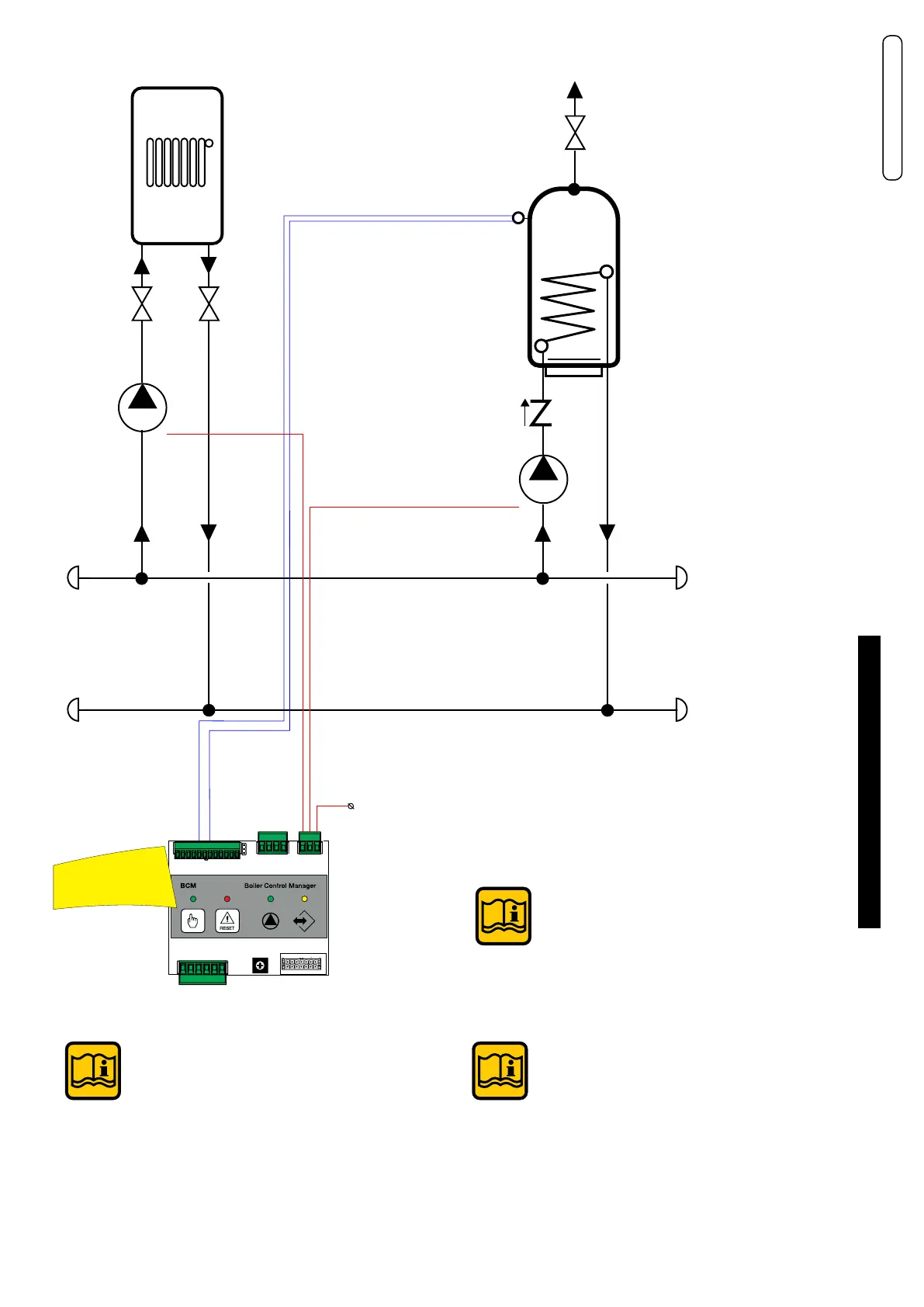
with direct zone and DHW production.
secondary loop
Note:
In case of installation with single boiler, the above
connections must be made on the return
terminal board (BCM board) inside the boiler.
Note:
To congure cascade boiler management param-
eters, refer to the specic installation manual.
Note:
Illustrative diagram, consider the total nominal
ow rate, any check valves (not supplied), and
verify the eciency of the ow switches at each
ow rate in modulation.