Bulletin 30-20 — Page 13
© Copyright 2010, Unico, Inc.
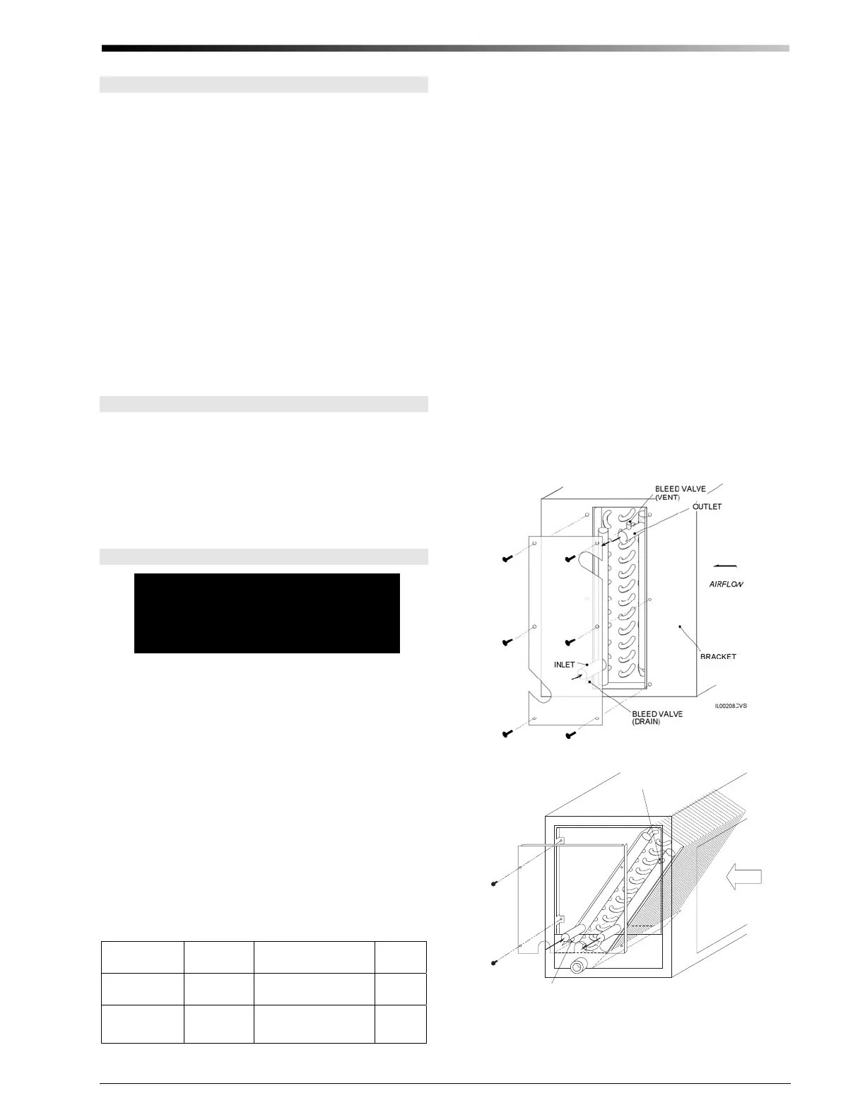
Water Connections
If you are installing the hot water coil, remove the side
coil access panel and cut away the insulation. Slide the
coil into the cabinet and secure with brackets supplied
with the hot water coil. Install the access panel after the
coil is in place.
All water connections are 7/8-inch (22mm) sweat con-
nections. Sweat the water connections, then fill the sys-
tem. Bleed the air from the coil by backing off the screw
inside the bleed valve for venting (Fig. 16).
If unit is in an unconditioned space below freezing, care
must be taken not to freeze the water in the coil. The best
method is to use a glycol-water antifreeze solution with a
freezing point below the coldest temperature expected.
After venting the chilled water coil, replace the access
panel and seal around the connections with the rubber
gasket provided.
Coil Cleaning
The coil should be sprayed with liquid detergent, or any
commercially available evaporator cleaner solution, tho-
roughly and rinsed thoroughly before installation to as-
sure proper drainage of condensate from the coil. This
will eliminate blowoff and assure maximum coil perfor-
mance. If not sprayed, approximately 50 hours of break-
in time are required to achieve the same results.
WIRING
WARNING
Disconnect electrical supply before
wiring unit to prevent injury or death
from electrical shock.
All electrical wiring must comply with all local codes
and ordinances. Blower module controls and compo-
nents are bonded for grounding to meet safety standards
UL Standard 1995 and CAN/CSA-C22.2 No. 236 and
are listed by ETL. All 50 Hz units are CE marked and
conform to the Low Voltage 73/23/EEC and EMC
89/336/EEC Directives.
Use a separate 1 ph - 230/208V – 60/50 Hz power
supply with a 15 amp breaker and appropriate wire
gauge per code.
Two different control boxes are available: one with a
variable ventilation speed control, one without. All stan-
dard units include a variable speed motor controller to
adjust the proper airflow for constant ventilation where
required by code or desired by the resident. The “ventila-
tion” speed is adjustable down to half airflow.
Control BoxMo-
del No.
Ventilation
Control
Availability
Wiring
Diagram
A00175-G02 Yes
Standard
(U.S., Canada)
Fig. 20
A00175-G03 No
Special Order
(Europe)
Fig. 21
The control box includes a 24-volt transformer, the ne-
cessary blower relays, and terminal blocks. Space is pro-
vided for a heat pump heating mode bypass relay
(shipped with heat pump cooling module). Space is also
provided for an additional double pole double throw
(DPDT) relay for wiring a boiler, pump, or valve if heat-
ing with hot water.
1. First, connect the motor plug to the wiring harness
from the control box.
2. Then, route the anti-frost switch lead wires (located
on the refrigerant coil) through the interior of the
modules to the control box. Connect the leads to
terminals #3 and #6 of the Low Voltage Terminal
Block. ALL DX COILS NEED THE FROST
SWITCH.
3. Next, connect the control wiring per figures 17
through 19. For units with electric duct heaters, refer
to Bulletin 30-34. Match thermostat anticipator set-
tings for combined amperage load of all compo-
nents, including electric heater contactors, to pre-
vent damage to thermostat.
4. Connect power supply to terminals L1 and L2 on
the high voltage terminal block. Connect a ground
(a) Hot Water Coil
BLEED VALVE
(VENT)
BLEED VALVE
(DRAIN)
IL00054b.CVN
IN
OUT
AIRFLOW
(b) Chilled Water Coil
Figure 16. Water Coil Connections
 Loading...