Bulletin 30-20 — Page 10
© Copyright 2010, Unico, Inc.
Return Duct
Unico supplies a return duct system but any return duct
system is acceptable provided the pressure loss does not
exceed 0.15 inches of water (37 Pa), including filters.
The return duct should have at least one 90° bend be-
tween the unit and filter box to reduce sound transmis-
sion directly from the unit.
The Unico Return Duct system has a single return that
includes the return air box with filter, the return duct,
and the return air adapter (refer to Fig. 3). Multiple re-
turns or extra long returns are possible so long as the
maximum pressure loss is not exceeded. For vertical
installations or tight spaces it may be necessary to fabri-
cate a return duct system from duct board or lined metal.
The typical return duct is 10-foot (3 m) in length so it
may have to be cut to avoid bunching if the distance to
the unit is significantly less than 100-inches. The mini-
mum length should be 7-feet (2 m). When given a
choice, the shorter distances should be avoided as this
may increase sound transmission from the unit.
Cut an opening for the return box as specified in Table 1.
For the 2430 and 3642 if the joists or studs are on 16-
inch (410mm) centers, there is no need to build a frame
to hold the return air box. Otherwise, it will be necessary
to construct a frame around the opening. For the 4860
return, it will almost always be necessary to cut and
header at least one joist.
Center the return air box so the filter frame flange covers
all the gaps and make sure the flange is flush against the
wall or ceiling. Install the return air box against the
frame using nails or screws.
Screw holes are provided in the return air box. Use the
holes nearest the corners. The other holes are for mount-
ing the filter grille. See Fig. 14.
FRAMING
RETURN AIR BOX
FILTER FRAME
FILTER
FILTER GRILLE
IL00048.CNV
Figure 14. Return Air Box and Filter
Install filter frame into the return air box using four nails
or screws. Use the holes furthest from the corners. Insert
filter and hold in place by rotating metal clips. Close
grille and secure with clips.
Refer to Table 5 for correct Return Duct Adapter selec-
tion. Attach the proper return duct adapter to either the
Heating or Cooling Module. Then attach the return duct
to the adapter and to the return air box using the Q-bands
and Q-clips.
The return air adapter ships with an insulation blanket
that must be wrapped around the adapter. Tape the
seams with UL 181A aluminum tape.
Table 5. Return Duct Adapter
Unit Size
Blower Module +
Cooling Module
Heating Module
+ Cooling Module
4860 UPC-59-4860 UPC-104-4860
3642 UPC-59-3642 UPC-104-3642
2430 UPC-59-2430 UPC-104-2430
Multiple Returns
If more than one return is desired, Unico has designed a
return plenum (MR) module. The MR module is availa-
ble in two sizes: 2430 and 3660, and it includes a central
filter. The MR module is easily fitted to the air handling
unit and multiple return openings may be cut in the top
back or sides of the box. Refer to Bulletin 20-20.6, Re-
turn Plenum Module, for additional information.
PIPING
All piping must be in accordance with all local codes
and ordinances.
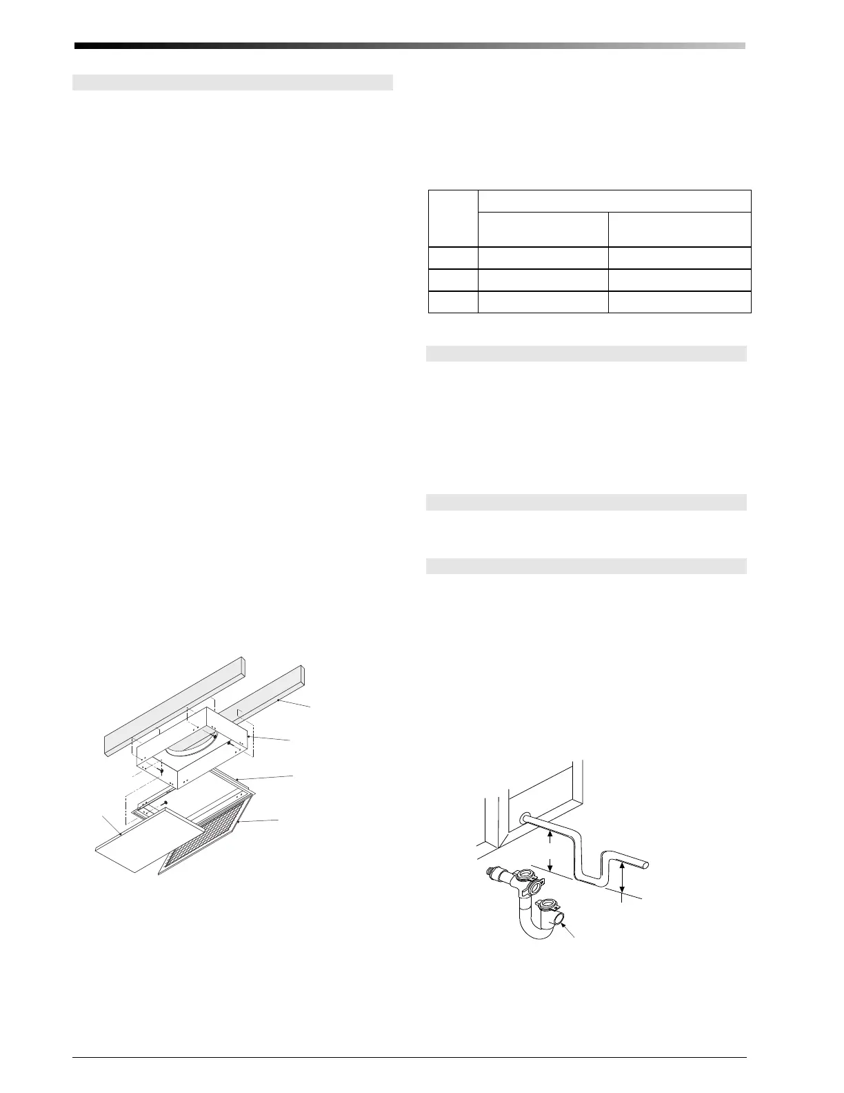
Condensate Lines
The primary drain pan condensate connection is a ¾-
inch (19mm) female pipe thread fitting and the second-
ary drain pan connection is a ¾-inch (19mm) PVC sock-
et fitting. Elevate the unit so the condensate lines are
pitched at least ¼-inch per lineal foot (20 mm per me-
ter). Trap the condensate line near the unit using U-trap
A00924-G03 as shown in Figure 15. In some cases it
may be necessary to wrap the condensate line near the
unit with insulation to prevent water condensation on the
outside of the pipe. In some climates or locations it may
be necessary to protect trap from freezing in the winter.
53/8
(137 mm)
21/4
(57 mm)
Pitch ¼ inch per foot
(2 cm per m)
IL00046a.cvx
U-TRAP (A00924-G03)
shi
ed wi
h MC modules
Figure 15. Typical Condensate Trap
Do not trap the secondary drain line and do not terminate
line into the primary drain line. Run secondary drain line
so that any drainage will be immediately known without
causing damage to property. A typical location is to ter-
 Loading...