Bulletin 30-20 — Page 9
© Copyright 2010, Unico, Inc.
DUCT CONNECTIONS
Supply Plenum
Unico has a complete line of round and square plenum
adapters available as shown in figures 10 and 11. In
addition, all blowers include a restrictor plate to be in-
stalled between the supply adapter and the unit. The
purpose of the restrictor plate is to eliminate objectiona-
ble outlet noise because the blower is delivering more
air than required. In most cases where the maximum
airflow is required, the restrictor may be omitted.
To attach the plenum adapter, first install the restrictor
plate. Then install the adapter with eight (8) sheet metal
screws as shown in Fig. 12. Sheet metal screws for in-
stalling both are provided with the blower.
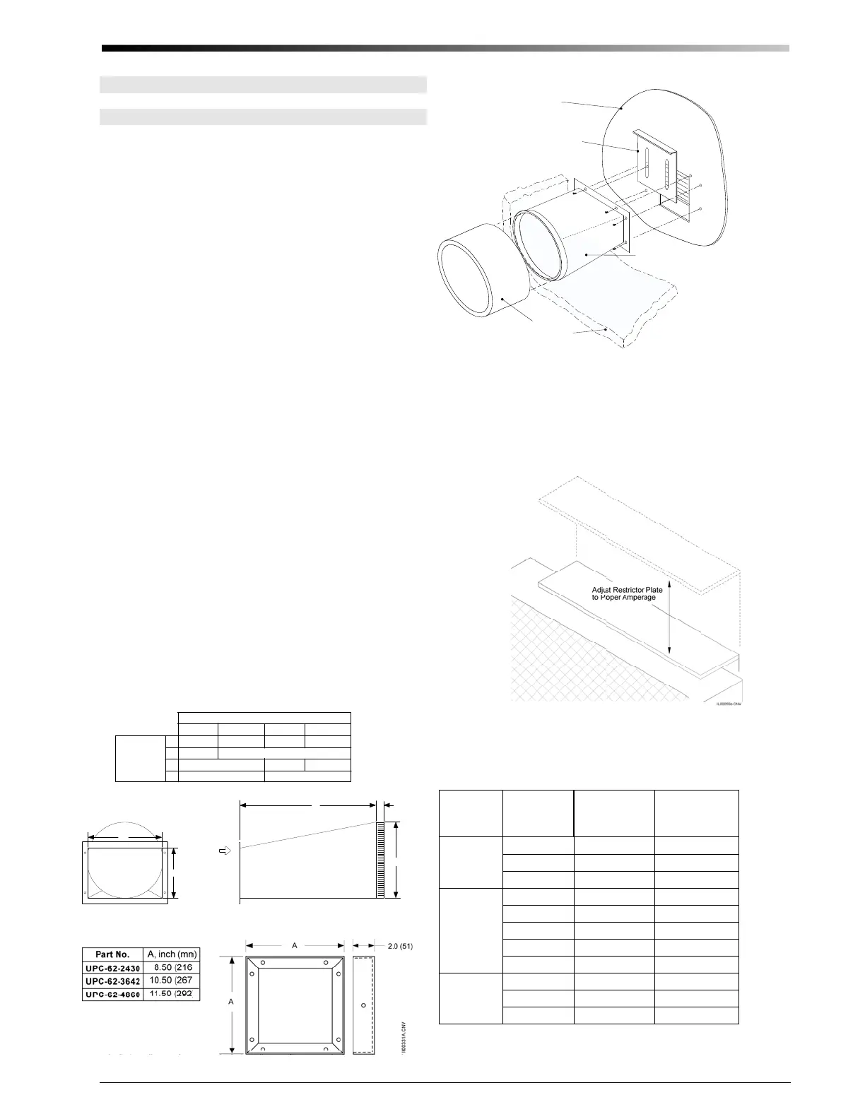
The restrictor plate is used to set the system airflow (see
Fig. 13). The full open position corresponds to the high-
est airflow the installed duct system will allow. Set the
restrictor plate to the full open position and measure the
system airflow. The required system airflow is 200-250
CFM per nominal ton (27-34 L/s per nominal kW).
Measure the motor amperage and use this to ensure the
200-250 CFM per nominal ton (27-34 L/s per nominal
kW) has been achieved. If elevated sound levels are no-
ticed at the outlets and there is more that 250 CFM per
nominal ton (34 L/s per nominal kW), the airflow may
be reduced with the restrictor plate. Always measure the
system airflow by the motor amperage (see Table 4).
Refer to the airflow-amperage charts provided with the
blower.
Note: Do not use restrictor plate to adjust
plenum static pressure. Adjust the restrictor
to the proper amperage. This will assure
proper airflow.
Attach the plenum to the adapter by inserting it over the
supply adapter. If using sheet metal duct, use three (3) or
four (4) equally spaced sheet metal screws or nails to
secure the duct to the supply adapter. Then tape around
the seam with UL 181A aluminum tape. Then wrap the
outside of the plenum adapter with the supplied blanket
insulation and secure the insulation seams with UL 181A
tape.
Figure 13. Restrictor Setting
Blower
Module
Restrictor
Plate
Plenum Adapter
Plenum
Insulation Wrap
IL00308.CVX
Figure 12. Supply Plenum Adapter Installation
Table 4. Approximate Amperages at Given Airflows
Unit Size
Airflow,
CFM (L/s)
MBxxxxL
Amps
@230V †*
MBxxxxL+CB
Amps
@230V †
4860
1250 (590)
4.1 4.1
1000 (470) 3.5 3.3
800 (380) 3.1 2.8
3642
1000 (470) 3.9 3.7
900 (420) 3.6 3.4
800 (380) 3.2 3.2
700 (330) 3.0 2.9
600 (280)
2.8 2.7
2430
600 (280)
2.2 1.9
500 (240)
2.0 1.6
400 (190)
1.8 1.4
* multiply by 1.1 if 208V
† for more exact airflow use the chart included with the blower
B
A
D
L
1 (25)
crimped
I
L
0
0
2
8
6
.
c
n
v
AIRFLOW
Model, UPC-61-
1218
2430
10 (254)
3642
4860
7.16 (182)
10.13 (257)
18 (457)
9 (229)
A
B
Dimension,
inch (mm)
6.5 (165)
6 (152)
3.25 (83)
6.38 (162)
D
L
7 (178)
12 (305)
Figure 10. Round Supply Plenum Adapter Dimensions
Figure 11. Square Supply Plenum Adapters
 Loading...