Bulletin 30-20 — Page 4
© Copyright 2010, Unico, Inc.
UNIT ASSEMBLY
The units may be assembled either horizontally or verti-
cally. Refer to Fig. 1 for your particular flow arrange-
ment. Assemble the units’ two modules at a time. If you
use a refrigerant coil, the anti-frost switch wires must be
routed to the control box as you connect the modules.
Anti-Frost Switch Wires
Remove the coil access panel and unravel the anti-frost
switch wires. If you use a heating module, feed the wires
under the hot water coil support channel. Then feed the
wires through the bushing in the motor partition panel.
After routing the wires through each module, connect the
modules together.
Fastening Modules Together
To fasten the modules together tilt the units to insert the
connection flange over the mating flange as shown in
Fig. 4. It may be necessary to squeeze the units together
as you are inserting the flange to compress the rubber
gaskets. If the hook flange has a small gap, use a large
flat bladed screwdriver to pry the gap apart. Secure the
modules together with the latches, compressing the
gasket further.
IL00009.CVS
Figure 4. Module Flange Connection
EC Motor Temperature Limits
The Unico EC motor includes an electronic circuit board
that is sensitive to overheating if the air temperatures
surrounding the motor are above a certain value. The
motor will not function above its maximum operating
temperature and will have some reduction in motor life
between the maximum operating temperature and the
recommended temperature limit. Depending on the ap-
plication, this may or may not be acceptable.
Recommended Temperature Limit
For maximum motor life, we recommend that the Unico
EC motor be limited to applications with less than 130°F
(54°C) air temperature. Therefore, the Unico EC motor
can be used with all heat pump and electric heating ap-
plications without problem. It may also be installed with
a hot water coil with air temperature leaving the coil less
than 130°F (54°C). This is generally with water tempera-
ture less than 135°F (57°C) but it depends on the water
and air flow. Consult the hot water coil specifications to
determine air temperatures based on water flow and air
flow rate.
Maximum Operating Temperature Limit
The absolute limit for the motor is 158°F (70°C) air
temperature at which point the motor will automatically
begin to slow down. The motor may be used in applica-
tions with air temperature around the motor between 130
to 150°F (54 to 65°C), typical for boiler systems with
water temperatures between 135 and 160°F (57 to
70°C). However, expect the life of the motor to be re-
duced by as much as 50%. In most applications, with
unit operating intermittently, the amount of time that the
motor operates in heating is very small so the reduction
in motor life will not be significant. Only in long conti-
nuous heating applications, will the reduction be notice-
able. The reduction in motor life can be further mini-
mized by using setback boiler temperatures while operat-
ing with maximum airflow at the highest water tempera-
tures.
Horizontal Installations
Most systems are installed in the horizontal configura-
tion, with the air going from right to left when looking at
the connections (as shown in figure 1). All the modules
are factory set for horizontal airflow. It is not recom-
mended to flip the cooling module to reverse the flow
direction of the air. When connecting the modules be
sure to arrange the heating module on the inlet (return)
side of the cooling module.
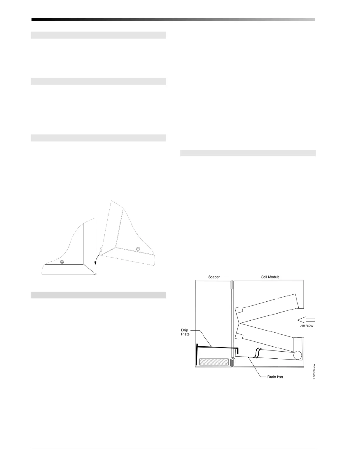
The 4860 cooling module also includes a spacer module
which has a small drip shelf (shipped loose) that must be
installed on the air exit side of the drain pan (shown in
figure 5).
When installing the heat module or return air plenum
module upstream of the cooling module, it is necessary
to first install a hook flange to the bottom of the cooling
coil (Figure 6).
Figure 5. 4860 Drip-plate installation (horizontal applica-
tions only)
 Loading...