Bulletin 30-20 — Page 14
© Copyright 2010, Unico, Inc.
wire to equipment grounding on the side of the con-
trol box near the incoming power opening.
WARNING
Be sure to insulate the unused trans-
former lead to prevent injury or death
from electrical shock.
The low voltage transformer is factory set for a pri-
mary voltage of 230V. If power supply is 208V, re-
move ORANGE lead from L2 terminal and connect
RED lead to L2. Insulate the connector on the un-
used wire lead.
TYPICAL
THERMOSTAT
COMMON
COMPRESSOR
POWER
FAN
UNICO SYSTEM
AIR HANDLER
OUTDOOR
CONDENSING
UNIT
COMPRESSOR
HEAT
IL00255.CNV
2
3
4
5
6
1
7
G
Y
R
W
Y
C
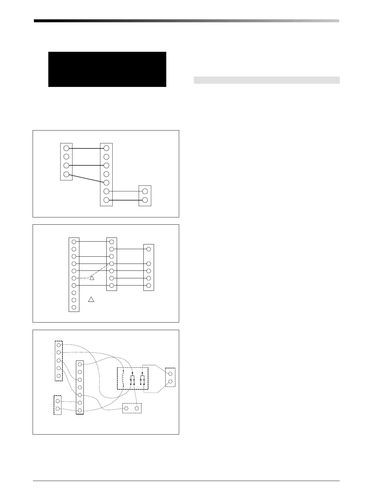
Figure 17. Cooling-only control wiring
W
Y
R
O
X
2
3
4
5
6
7
1
L
G
Y
B
R
O
W3
X
W2
E
TYPICAL HEAT PUMP
THERMOSTAT
POWER
COMMON
COMMON
REV. VALVE (COOLING)
COMPRESSOR
POWER
FAN
UNICO SYSTEM
AIR HANDLER
OUTDOOR
CONDENSING
UNIT
1
EMER. HEAT
REV. VALVE (HEATING)
AUX. HEAT
AUX. HEAT
DEFROST HEAT
REV. VALVE
COMPRESSOR
1
WIRING DIAGRAM AS SHOWN IS FOR A REVERSING VALVE THAT IS
ENERGIZED IN COOLING MODE. WHEN VALVE IS ENERGIZED IN
HEATING MODE, USE THE "B' TERMINAL ON THE THERMOSTAT,
INSTEAD OF THE "O" TERMINAL.
I
l
0
0
0
6
2
a
.
C
V
N
Figure 18. Heat pump control wiring (without electric heat)
T
T
AQUASTAT
Honeywell R8222D1014 or Steveco 90-340
Relay plus Enclosure(or equal)
DPDT RELAY
G
X
R
Y
W
Y
C
2
3
4
5
6
7
1
T
T
BOILER OR
PUM P
Honeywell T87F T hermostat w i th Q539A
subbase (or equal)
POW ER
COMM ON
COMMON
HEAT
COMPRESSOR
POW ER
FAN
UNICO SYSTEM
AIR HANDLER
OUTDOOR
CONDENSING UNI T
I
L
0
0
1
3
0
c
.
C
V
N
1
4
3
2
6
5
THERMOSTAT
Figure 19. Cooling with Typical Hot Water Heating control
wiring (with optional aquastat)
The controller is set at the factory to provide constant
ventilation anytime the speed switch is turned in the ON
position. To turn on or off this feature at the thermostat
refer to the supplementary wiring diagrams for instruc-
tions (located near the end of this document).
Ventilation Speed Mode
The Unico System is factory configured to energize the
fan at full speed whenever there is a call for heat or cool,
or when the fan switch is set to ON. The unit can be set
for constant ventilation at the air handler whenever the
fan switch is in the AUTO position and there is no call
for heat or cool. There is a variable speed switch on con-
trol box which can be adjusted for the desired speed. The
variable speed control is set to the OFF setting at the
factory. To enable this feature, we recommend setting it
to the lowest speed (fully clockwise).
In this configuration, the ventilation speed can only be
adjusted or turned off or on using this switch. This can
be inconvenient if the unit is not easily accessible. To
allow the user to turn the ventilation speed mode on or
off at the thermostat using the FAN switch, the factory
wiring can be modified as shown in figures 22 to 25,
depending on the configuration. To accomplish this, two
wires inside the control box must be moved as described
on the wiring schematics.
 Loading...