Bulletin 30-20 — Page 2
© Copyright 2010, Unico, Inc.
Each module is available in three sizes: 2430, 3642, and
4860. Models with a 3660 model number denote that the
particular unit piece may be used with the 3642 or 4860
model.
There are three basic modules: a blower module, a cool-
ing module, and a heating module. The blower module
includes the blower wheel, blower housing, motor, and
electrical control box. The cooling module includes a
cooling-only refrigerant coil, a heat pump coil, or a
chilled water coil. The heating module is supplied as an
empty cabinet with room for a slide-in hot water coil.
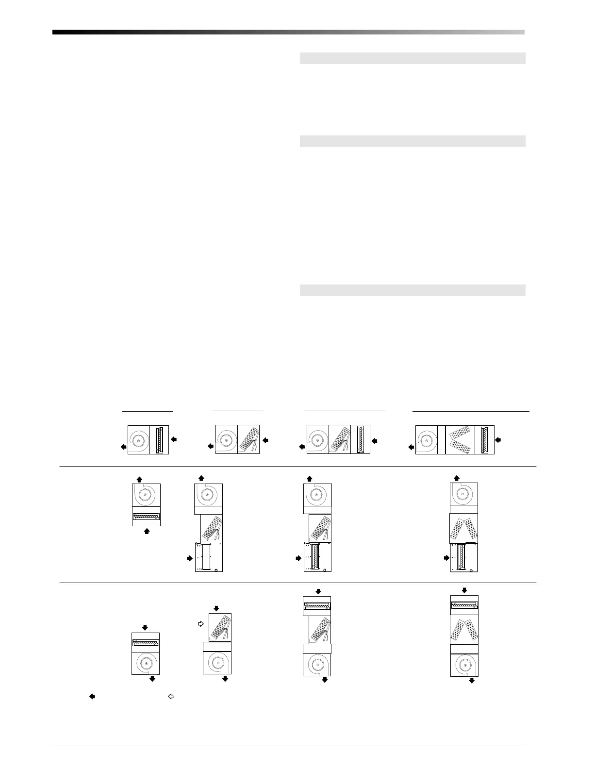
The modules can be arranged to provide only the options
needed as shown in Figure 1 (with details on pages 26
and 27). Heating-only systems require the blower
module, the heating module, and a hot water coil. Cool-
ing-only systems include the blower module and a cool-
ing module. For heating and cooling all the modules are
combined with coils. The system may even be used for
ventilation-only, using just the blower module.
Unico designed and built blowers feature direct drive
motors or EC motors and are located in the air stream.
Each blower wheel is balanced to Unico specifications.
The blowers feature a quick twist-and-lock motor mount
for easy maintenance (see page 16). The motorized
blower assembly consists of the motor, which is
mounted to the inlet ring, and the wheel, which is
mounted to the motor shaft.
OPTIONS
Other options and modules are also available to add ad-
ditional features or to simplify installation. These in-
clude an electric duct heater, multiple return plenum, and
a vertical plenum stand. Please refer to the latest Unico
Catalog for information on these and other options.
UNPACKING
All modules are inspected prior to shipping and are care-
fully packaged in individual cartons. Inspect all cartons
prior to unpacking. Notify carrier of any damage.
Open each carton to remove the modules. Inspect unit
for visible signs of concealed damage and notify carrier
of any such damage.
All materials are sold FOB Factory and it is the respon-
sibility of the consignee to file any claims with the deli-
vering carrier for materials received in damaged condi-
tion.
LOCATION
Locate the air handler to minimize the number of plenum
elbows and fittings while keeping the supply duct runs as
short as possible. (See Bulletin 40-30, Component Duct
Layout Design). Provide minimum clearance on both
sides for servicing the unit as shown in Fig. 2.
Heating and Cooling
Horizontal
Flow
Vertical
Counter-Flow
Vertical
Up-Flow
IL00010d.CVN
Heating Only
Cooling Only
No
mal Ai
Inle
/
u
le
ional Ai
Inle
Blower Module`
Spacer Module
Cooling Module
Vertical Plenum
Module (with Hot
Water Coil)
Vertical Plenum
Module (without Hot
Water Coil)
Spacer Module
Heating Module
(with Hot Water Coil)
Heating and Cooling (M4860)
Figure 1. Basic Module Arrangement (refer to detail figures shown on Pages 26 and 27)
 Loading...