Bulletin 30-20 — Page 3
© Copyright 2010, Unico, Inc.
If installing the unit in an attic, avoid placing the unit
above a bed. The ideal location is above a central hall, a
closet, a bathroom, or any normally unoccupied space.
The unit can also be installed in a closet, crawlspace, or
basement. If the local codes allow, the unit may be in-
stalled in the garage provided the ductwork is well
sealed, especially the return duct. Although the unit is
not designed for outdoor use, it may be located outside
provided adequate weather protection is used; typically a
roof installation requires mounting on blocks with a
sheet metal cover or cap to protect the unit from rain and
extreme weather conditions.
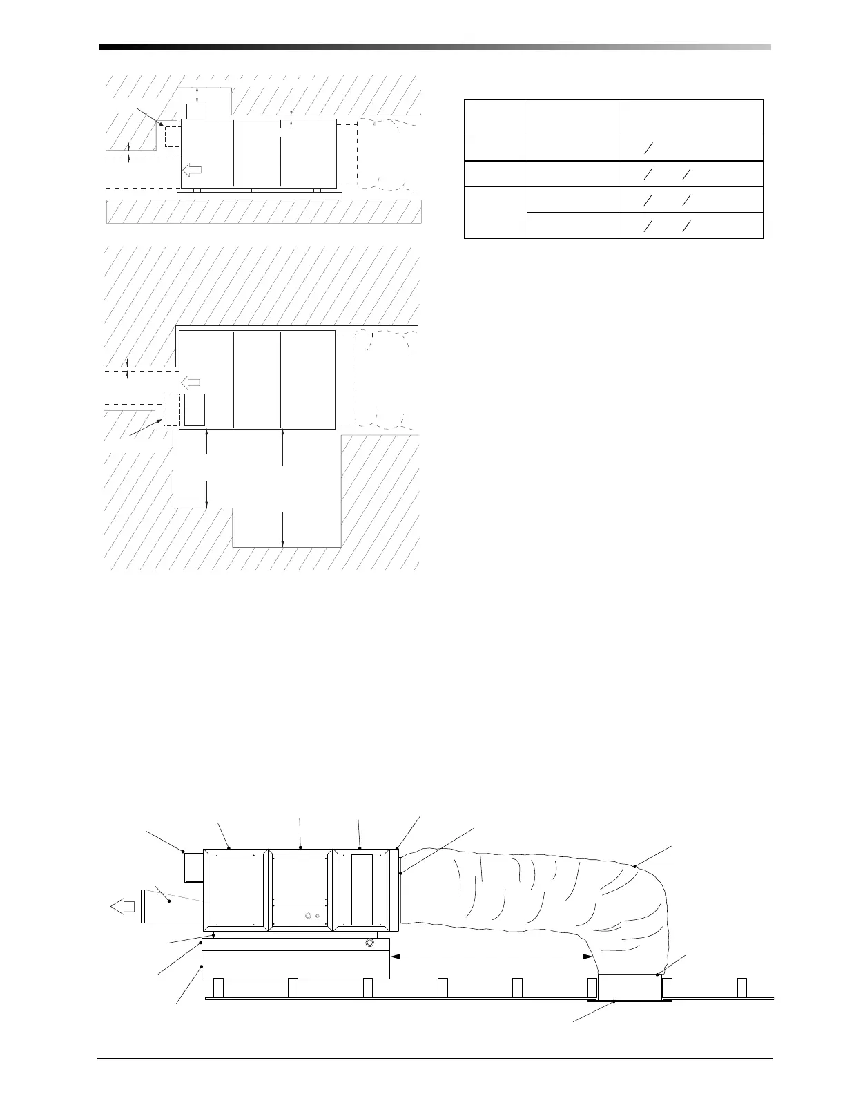
Be sure to position the return air box and filter near the
unit allowing at least one 90° bend in the return duct for
proper acoustical performance (refer to figure 3 for a
typical horizontal attic installation). The section on Re-
turn Air Ducts in the manual provides more details.
All modules except the MC4860 cooling module are
designed to fit through a 14-inch (356 mm) opening,
typical of a joist spaced at 16-inch (406 mm) center dis-
tance. The MC4860 module requires an 18.5-inch (470
mm) opening. If no access is provided, an opening must
be cut. It is suggested to use the opening required for the
return air box, especially in an attic installation. The
opening for the return air box is listed in Table 1. If the
joists or studs are less than 16-inches (406-mm) center-
to-center or running the wrong direction it will be neces-
sary to cut and header the joists.
Return Duct
IL00037b.CNV
Top View
6 (152) Minimum
Service clearance:
30 (762) for MH/MC2430
42 (1067) for MH/MC4860
1 (25) Minimum
Supply Plenum
Secondary Drain Pan
Return Duct
Supply Plenum
1 (25) Minimum
5 (127) Minimum for Control Box Cover Removal
Air Flow
Air Flow
MBxxxxx
Side View
1 (25) Minimum
All dimensions in inches (mm).
Optional Control Box
Placement
Optional Control Box
Placement
MCxxxx MHxxxxx
MBxxxxx MCxxxx MHxxxxx
6 (152) Minimum
20 (508) side
clearance for service
Figure 2. Minimum Clearances
Table 1. Return Air Box Opening
Models
Return Air Box
Part No.
Size of opening
inches (mm)
2430 UPC 01-2430
14
3
8
× 25 ½ (365 × 648)
3642 UPC 01-3642
14
3
8
× 30
1
2
(365 × 775)
4860
UPC-01-4860
24
3
8
× 30
1
2
(619 × 775)
UPC-01-4860NC
20
3
8
× 30
1
2
(518 × 775)
Cooling
Module
(MCxxxxx)
Blower
Module
(MBxxxxx)
Heating
Module
(MHxxxxx)
Return Air Adapter
(UPC 104-xxxx)
Band (supplied with return air box)
Return Air Duct
(UPC-04-xx-1)
Return Air Box
(UPC-01-xxxx-1)
Plenum
dapter
(UPC 61-xxxx)
Isolation
Pads
Secondary
Drain Pan
(UPC 20 or 24)
Platform
Typical 10 foot (3.6 m) Return Duct
Use at least one 90° bend.
IL00039c.CVS
Control
Box
Band
Fi
ure 3. T
ical Horizontal Attic Installation
 Loading...