Bulletin 30-20 — Page 7
© Copyright 2010, Unico, Inc.
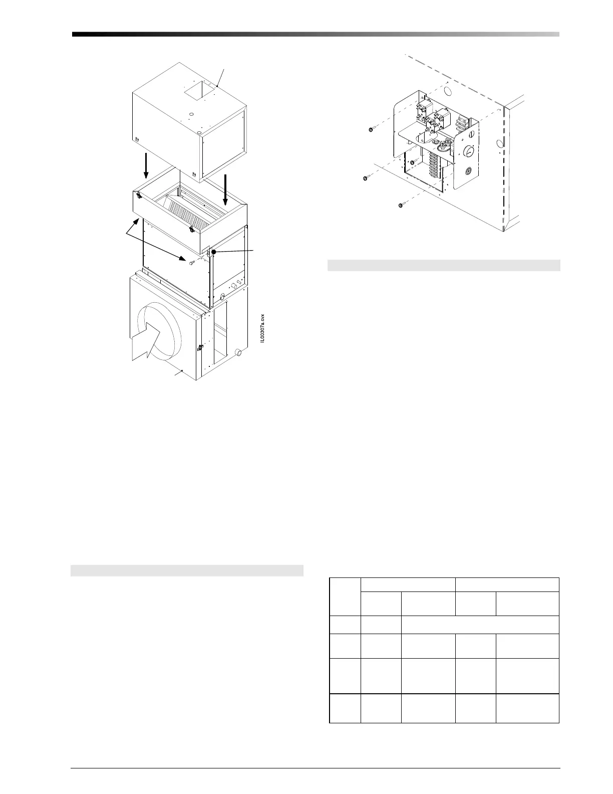
Blower
Module
Return Air
Ada
er
Airflow
Corner
Bracket
(2 plcs)
Attach
both
corner
brackets
(not used
on 4860)
STEP 5. Place the Spacer Module on top of the cooling
coil. Then place the Blower Module on top of it.
Secure both modules with latches.
Heating-Only Systems For heating-only systems, the
installation is similar to the cooling-only or heating-and-
cooling system, except that the cooling module is re-
moved from the system.
For the 2430 and 3642 systems with the MV unit, use a
vertical spacer kit such that the spacer overhangs the
back of the vertical plenum and the filter access is not
covered over. Insulation gasket tape, which is shipped
with the spacer module, is installed on the opening of the
spacer module.
Control Box
The control box is shipped with the blower module. It
can be installed on either the discharge side of the blow-
er cabinet or on top of the blower cabinet, depending on
what is most convenient.
To install, first remove the two knockouts on the side or
top of the cabinet, where it will be installed. Mount the
control box using four (4) sheet metal screws as shown
in Fig. 7. Feed the wires from the anti-frost switch
through the hole and bushing nearest the side of the unit
and connect the leads to low voltage terminals 3 and 6.
The motor wiring harness will slip through the other
hole. Then simply connect the plug on the motor wiring
harness. (For additional information see section on wir-
ing.)
I
L
0
0
3
3
2
.
C
N
V
Figure 7. Mounting the Control Box.
Secondary Drain Pan
Where an overflow of condensate could cause water
damage, a secondary drain pan MUST BE INSTALLED.
Place the drain pan on the mounting base, platform or
angle iron support frame. Be sure to allow enough room
for the drain line and connection (refer to Table 3). The
assembled unit should be placed over the secondary
drain pan supported by rails with rubber pads for isola-
tion to raise the unit above the 1.5-inch (38mm) sides of
the secondary drain pan.
Table 2 shows the secondary drain pans to be used for
horizontally mounted modules. For vertical up-flow ar-
rangements that use the cooling module, the 2-module
drain pans can be used where space permits and the re-
turn air is entering from the side. These pans would be
over-sized compared to the footprint of the cooling
module. If a smaller drain pan is necessary it should be
fabricated to be at least ½-inch (12.7 mm) larger on each
side of the bottom module.
For vertical down flow (counter flow) arrangements it is
difficult to provide a secondary drain pan because of the
blower discharge at the bottom. The secondary drain pan
must be fabricated with an opening for the blower dis-
charge and plenum adapter and still provide a sealed
drain pan.
Table 2. Secondary Drain Pan Dimensions, inches (mm)
Unit
Size
2 Modules 3 Modules
Part No.
Dimensions
inches (mm)
Part No.
Dimensions
inches (mm)
1218 UPC-94
40 x 22 (1016 x 559)
2430 UPC 20B
27 × 29.5†
(686 × 749)
UPC 20C
27 × 41.75†
(686 × 1060)
3642
UPC 24B
40 × 29.5†
(1016 × 749)
UPC 24C
40 × 41.75†
(1016 × 1060)
4860 UPC-24C
40 × 41.75†
(1016 × 1060)
UPC-24D
40 x 54†
(1016 x 1372)
† NOTE — The drain fitting extends 7/8 inch (22 mm) beyond this dimension.
 Loading...