- 5A at 250Vac/30Vdc relay
- 5A/250Vac relay
- 5A at 250Vac/30vdc relay
Standard:
100...240Vac ± 10%
Optional:
11...27Vac/Vdc ± 10%
Max. power 8VA; 50/60 Hz
4 • CONNECTIONS
• Outputs
6
5
4
3
2
1
7
8
9
10
11
12
18
17
16
15
14
13
19
20
21
22
23
24
Out2
Out1
• Power Supply
23
24
~
~
TOP
Out3
!
PWR
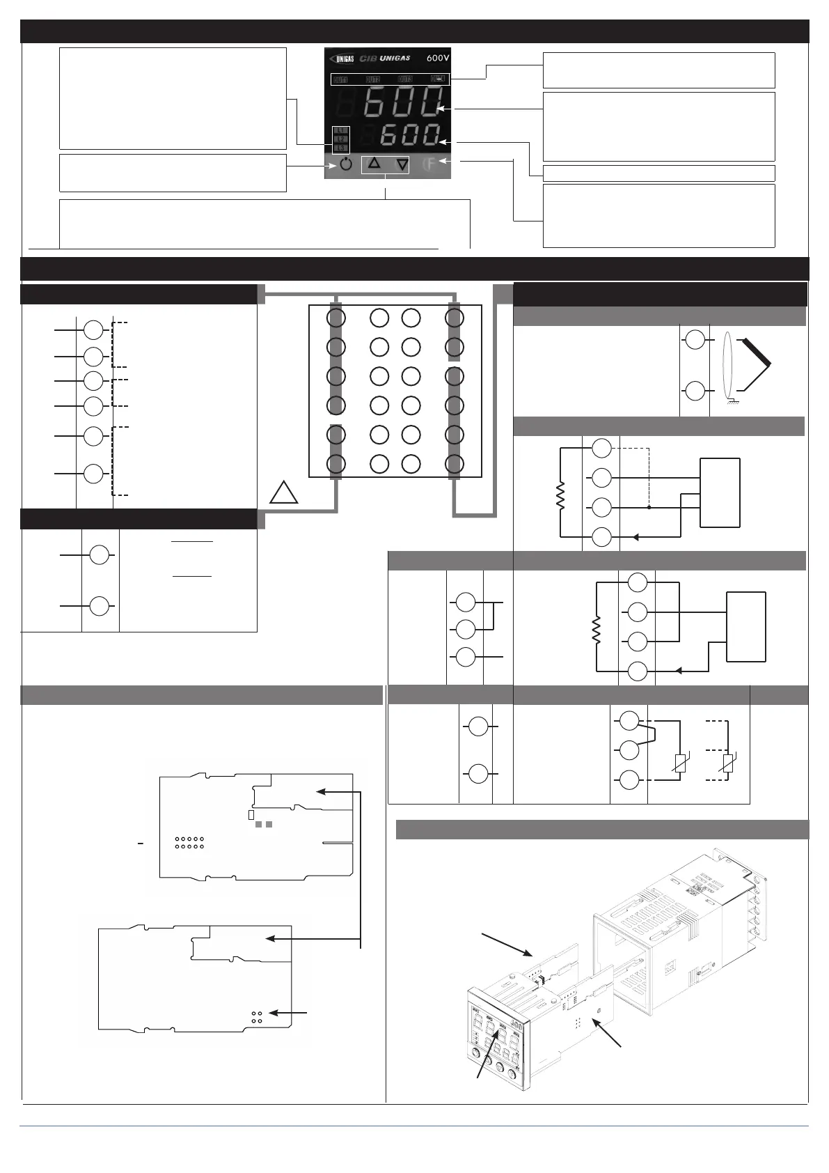
3 • DESCRIPTION OF FACEPLATE
4...20mA
Connect at 20mA input
Use wires of
adequate diameter
(min. 1mm
2
)
PT100, JPT100,
PTC, NTC
• Pt100 / PTC / NTC
3
1
2
Pt100 3 wires
PTC / NTC
/ Pt100 2 wires
Available thermocouples:
J, K, R, S, T
(B, E, N, L, U, G, D, C custom
linearization is available)
- Observe polarities
- For extensions, use the correct
compensating cable for the type
of TC used
+
-
• TC Input
2
1
4
2
3
1
+ 24V o 15V
VT
-
+
+
S
-
Ri = 50Ω
4
2
3
1
+ 24V o 15V
VT
-
+
+
-
Ri = 50Ω
T
T
• Linear input with 3-wire transmitter
• Inputs
• Input 1 linear with transmitter 2 wires
Linear
input
in dc
current
20mA,
Ri = 50Ω
Linear input in
dc voltage
60mV, 1V
Ri > 1MΩ
5V, 10V
Ri > 10KΩ
2
1
+
-
• Linear input (I)
4
1
2
-
+
• Linear input (V)
19
21
20
22
6
5
“Inc” and “Dec” key
Press to increment (decrement) any numerical parameter •• Increment (decrement) speed
is proportional to time key stays pressed •• The operation is not cyclic: once the maximum
(minimum) value of a field is reached, the value will not change even if the key remains pressed.
Automatic/Manual adjustment selection
Active only when PV display visualises the process
variable (button pressed for at least 5 sec.)
Function indicators
Indicates modes of operation
L1 MAN/AUTO = OFF (automatic control)
ON (manual control)
L2 PRE-HEATING = ON (running)
L3 SELFTUNING = ON (enabled Self)
OFF (disabled Self)
PV Display: Indication of process variable
Error Indication: LO, HI, Sbr, Err
LO= the value of process variable is < di LO_S
HI= the value of process variable is > di HI_S
Sbr= faulty sensor or input values higher than max. limits
Err= PT100 third wire opened for PT100, PTC or input
values lower than min. limits (i.e.: TC wrong connection)
Function key
Gives access to the various configuration phases ••
Confirms change of set parameters and browses next or
previous parameter (if Auto/Man key is pressed)
SV display: Indication of setpoint
Indication of output states
OUT 1 (AL1); OUT 2 (OPEN); OUT 3 (CLOSED)
• Device structure
• Identification of boards
Select signal at
contact 3
CPU board - Component side
PT100
+VT
24V
15V
10V
5V
1,23V
R20
S2
N.B. : you can keep the OUT1 relay energized at power-up by
inserting jumper S2 and removing resistance R20.
IN/OUT boards
(see appendix)
Power board - Solder side
Select transmitter voltage
DISPLAY
POWER
CPU
2 80379_MHW_600V-T73_06-2012_ENG