M12927CA
CONNECTIONS DIAGRAM
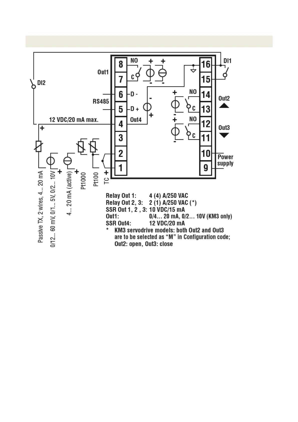
Probe connection:
• PT1000/NTC/PTC: between terminal 3 and 2
• PT 100: between terminal 3 and 2 with terminal 1
• Passive pressure probe 0/4-20 mA: between terminal 4 ( + ) e 1 ( - )
Note: out4 must be activated ( IO4F must be setted to ON )
• Powered pressure probe 0/4-20 mA between terminal 4 (power supply), 2 ( negative) e 1 (positive)
Note: set IO4F to ON to activate Out4
Power supply connection:
• Neutral wire: terminal 9
• Phase: terminal 10 ( 100…240 Vac )
• Close terminals 15-16 to switch to the set point 2
Output connection:
• Channel 1: terminal 7 and 8 ( burner on – off )
• Channel 2: terminal 11 and 12 (servomotor opens)
• Channel 3: terminal 13 and 14 (servomotor closes)
4