PART II: INSTALLATION
16
GAS TRAIN CONNECTIONS
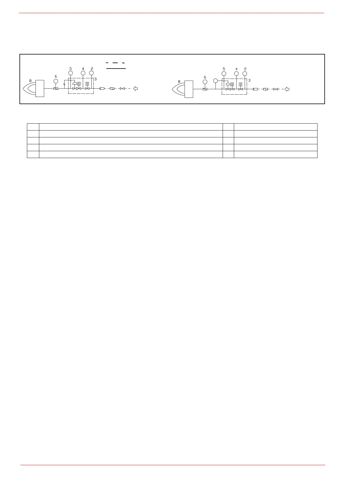
The diagrams show the components of the gas trai included in the delivery and which must be fitted by the installer.The diagrams are in
compliance with the current laws.
Gas train with valves group VGD and MBE with built-in gas pressure governor + gas leakage pressure switch (PGCP)
Legend
1 Filter 6 Butterfly valve
2 Pressure switch - PGMIN 7 Pressure transducer
3 Safety valve with built in gas governor 8 Main burner
4 Proving system pressure switch - PGCP 9 Antivibration joint (*optional)
5 Pressure switch PGMAX: mandatory for MBE, optional for VGD and MB-DLE 10 Manual valve(*optional)
M
PS PSLPSH
PT
7
MBE
1910
M
PS
PSL
PSH
VGD
1910
gas inlet
gas inlet
supplied by burner constructor
by others