11
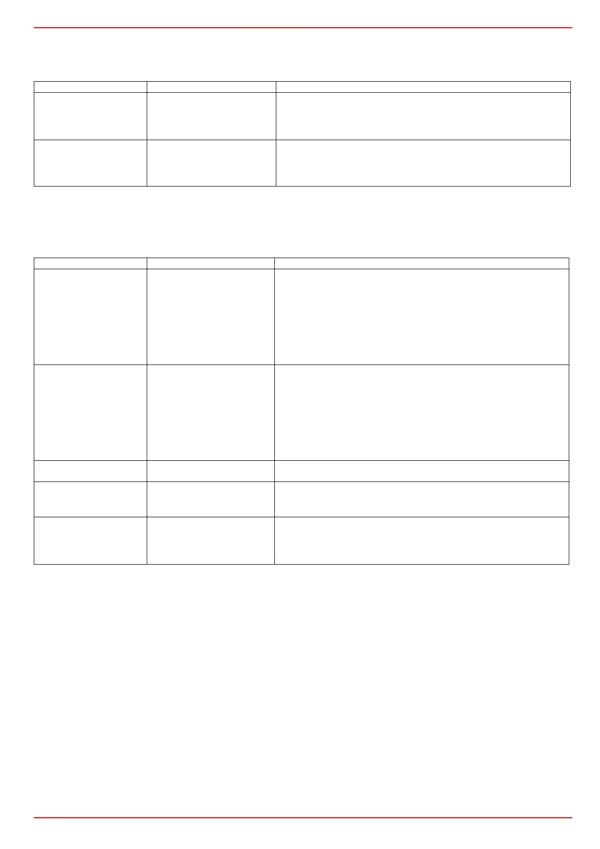
ConF > binF
This setting decides on the use of the binary inputsD1, D2, DG
b
(bold = factory settings)
ConF > dISP
.Both displays can be customized to suit your needs by configuring the displayed value, decimal, time out and blocking
(bold = factory settings)
Parameter Value Description
bin1
binary imput 1 (terminals DG
– D1)
0
1
2
3
0 =
without function
1 = set-point changeover (SP1 / SP2)
2 = l
set-point shift (Opr > dSP parameter = value of set-point modify)
3 = input alarm
bin2
binary imput 2 (terminalsк
DG – D2)
4
changeover of operating mode
DG-D2 open = modulating operation
DG-D2 close = 2 stage operation
Parameter Value Description
diSU
pper display (red)
0
1
2
3
4
6
7
Display value for upper display:
0 =
display power-off
1 = analog input 1 (InP1) value
2 = analog input 2 (InP2) value
3 = analog input 3 (InP3) value
4 = controller's angular positioning
6 = set-point valueв
7 =
end value with thermal shock protection
diSL
lower display (green)
0
1
2
3
4
6
7
Display value for lower displayЗ:
0 =
display power-off
1 = analog input 2 (InP2) value
2 = analog input 2 (InP2) value
3 = analog input 2 (InP2) value
4 = controller's angular positioning
6 = set-point valueв
7 =
end value with thermal shock protection
tout
timeout
0..180..250
time (s) on completion of which the controller returns automatically to the
basic display, if no button is pressed
dECP
decimal point
0
1
2
0 =
no decimal place
1 = one decimal place
2 = two decimal place
CodE
level lockout
0
1
2
3
0 =
no lockout
1 = configuration level lockout (ConF)
2 =
parameter and configuration level lockout (PArA & ConF)
3 =
keyboard lockout