PART II: INSTALLATION
26
Siemens CD attached to the burner
Configuration with separate electrical panel (optional)
The length of the electrical cables must comply with the provisions in the technical sheets of the equipment or the advice the company
gives at the time of the offer/contract.
Provide sufficient protections for cables and connectors, taking into consideration positioning spaces and the panel-burner tracing sur-
faces. Always consult beforehand the electrical drawings supplied in relationship to the topography of the feeding systems.
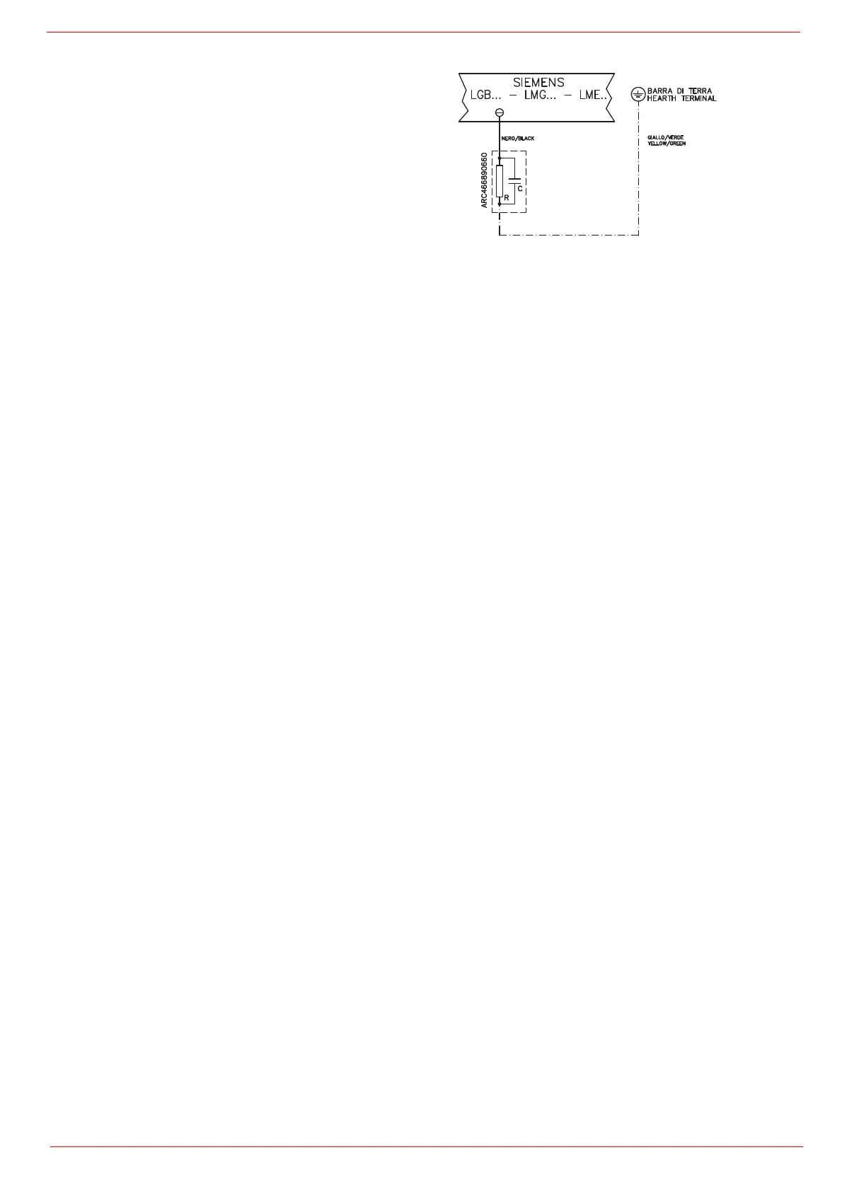
Key
C - Capacitor (22 nF , 250 V)
LME / LMV - Siemens control box
R - Resistor (1 MΩ)
M: Terminal 2 (LGB, LME), Terminal X3-04-4 ( LMV2x, LMV3x,
LMV5, LME7x)
RC466890660 - RC Siemens filter