INTRODUCTION ............................................................................................................................................................... 2
1 SAFETY INFORMATION ....................................................................................................................................... 5
1.1 INSTALLATION CONDITIONS ............................................................................................................................... 5
1.2 INSTALLING THE INSTRUMENT ........................................................................................................................... 5
1.3 POWER SUPPLY .................................................................................................................................................. 6
1.4 USED PRODUCTS ................................................................................................................................................ 6
2 UNDERTAKING AND WARRANTY .................................................................................................................... 6
2.1 LIABILITY .......................................................................................................................................................... 6
2.2 WARRANTIES ..................................................................................................................................................... 6
2.3 PATENT .............................................................................................................................................................. 7
3 COMPONENTS OF THE PQ SECURE SYSTEM ................................................................................................ 8
3.1 MEASURING DEVICE ........................................................................................................................................... 9
3.2 COMMUNICATION .............................................................................................................................................. 9
3.3 PORTABLE METER UNILYZER 900 / UNILYZER 900C / UNILYZER 902 ................................................................ 9
3.4 SOFTWARE ....................................................................................................................................................... 10
3.4.1 Server performance ..................................................................................................................................... 11
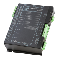
4 INSTALLING PERMANENT METER UP-2210 ................................................................................................ 12
4.1 LOCATION AND FITTING ................................................................................................................................... 12
4.2 INSTALLATION DIAGRAM ................................................................................................................................. 13
4.3 CONNECTION POINTS ........................................................................................................................................ 15
4.4 CONNECTION ALTERNATIVES ........................................................................................................................... 18
4.4.1 1-phase measurement with direct voltage and one CT (Line-to-neutral voltage) ....................................... 18
4.4.2 1-phase measurement with one PT and one CT .......................................................................................... 19
4.4.3 HV 3-phase measurement with 2 CT’s and 2 PT’s (Line-to-line voltages) ................................................. 20
4.4.4 HV 3-phase measurement with 3 CT’s and 2 PT’s (Line-to-line voltages) ................................................. 21
4.4.5 HV 3-phase measurement with 2 CT’s and 3 PT’s (Line-to-line voltages) ................................................. 22
4.4.6 HV 3-phase measurement with 3 CT’s and 3 PT’s (Line-to-line voltages) ................................................. 23
4.4.7 3-phase measurement with direct voltage, 2 CT´s (Line-to-neutral)........................................................... 24
4.4.8 3-phase measurement with direct voltage, 3 CT´s and neutral (Line-to-neutral voltages) ......................... 25
4.4.9 3-phase 4 wire measurement with 2 CT’s and 2 PT’s ................................................................................. 26
4.4.10 3 phase with 4 wire measurement with 3 CT’s and 2 PT’s ..................................................................... 27
4.4.11 3 phase with 4 Wire measurement with 2 CT’s and 3 PT’s .................................................................... 28
4.4.12 3 phase with 4 wire measurement with 3 CT’s and 3 PT’s ..................................................................... 29
4.4.13 3 phase with 4 wire measurement with direct voltage and 2 CT’s ......................................................... 30
4.4.14 3 phase with 4 wire measurement with direct voltage and 3 CT’s ......................................................... 31
4.4.15 SP 2CT 2PT ............................................................................................................................................ 32
4.4.16 SP 2CT DV ............................................................................................................................................. 33
4.4.17 HV/MV Earth fault monitoring via channel U4...................................................................................... 34
4.5 VECTOR GRAPH FOR CORRECT CONNECTION .................................................................................................... 35
4.6 RECOMMENDED PRACTICES ............................................................................................................................. 36
4.6.1 Impedance grounded 3-wire systems .......................................................................................................... 36
4.6.2 Effectively (directly) grounded 3-wire systems ........................................................................................... 36
4.6.3 Isolated (ungrounded) 3-wire systems ........................................................................................................ 37
4.6.4 Low voltage 4- or 5-wire systems ................................................................................................................ 37
4.6.5 Alternative connection option for MV/HV 3-wire systems .......................................................................... 37
4.7 DIGITAL INPUTS AND OUTPUTS ......................................................................................................................... 37
4.7.1 Connection of digital inputs ........................................................................................................................ 38
4.7.2 Connection of digital outputs ...................................................................................................................... 38
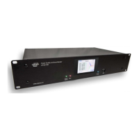
5 DISPLAY UNIT....................................................................................................................................................... 39
6 INSTALLING COMMUNICATION EQUIPMENT ........................................................................................... 40
6.1 ETHERNET ........................................................................................................................................................ 40
6.2 EXTERNAL MODEM .......................................................................................................................................... 40
 Loading...