ACCESSORIES
Section 8-17
The rotary option on the printer driver has to be set and the rotary has to be installed properly and
calibrated in order for this accessory to function correctly.
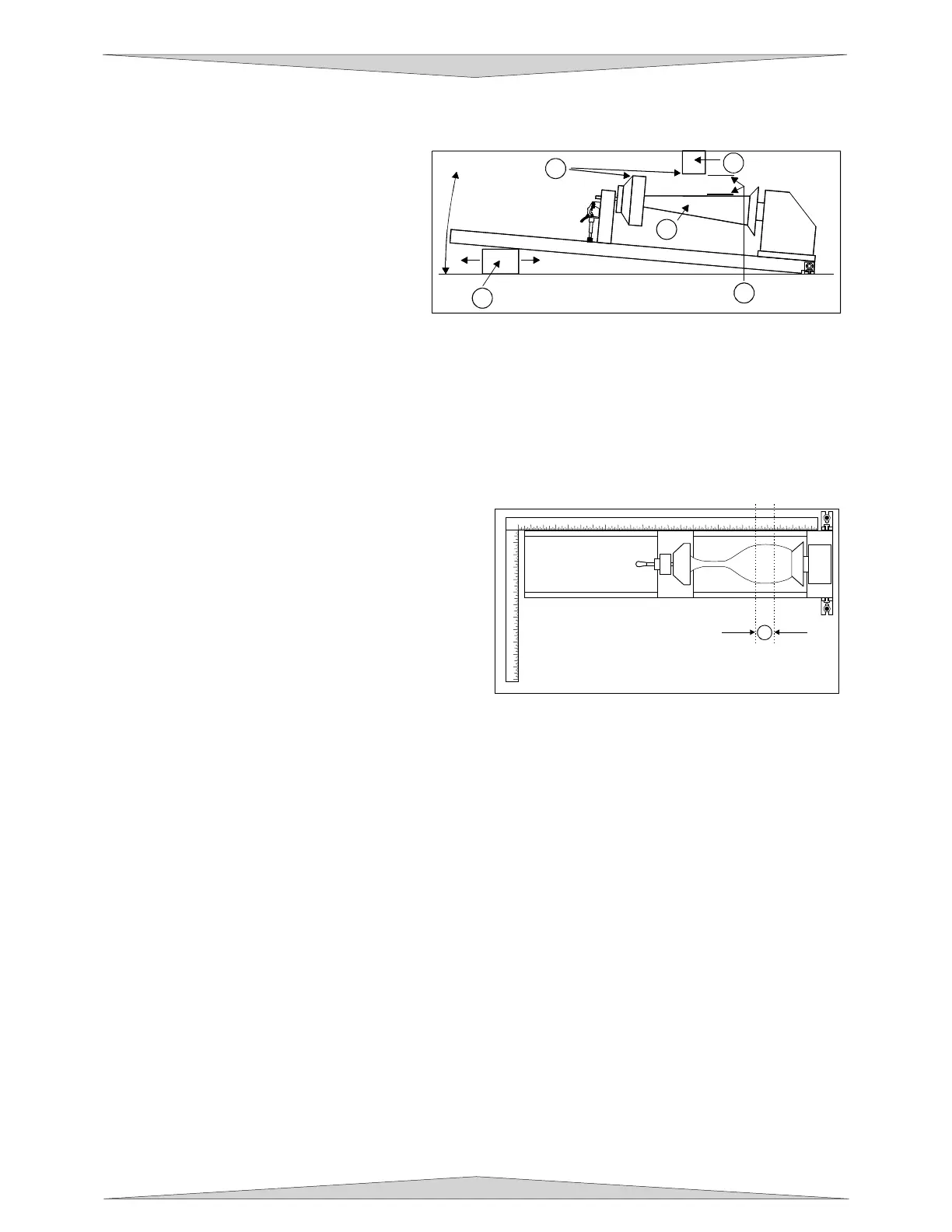
If engraving a tapered object (1), the Rotary
Fixture can be rotated to maintain proper
focus. To do this, lift up the left end of the
fixture and place some sort of spacer
underneath the fixture (2) to prop it up.
Slide the spacer left and right until the
surface of the object is parallel (3) to the
Focus Carriage. Be careful not to raise the
Rotary Fixture too high (5), otherwise parts
of it might interfere with the Focus Carriage
(4). NOTE: If you operate the fixture in this manner, you might need to taper your graphic in your
software so that it matches the taper angle of your object. Otherwise, your graphic might appear to be
tapered when it is engraved.
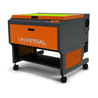
Determining Graphic Placement
We now need to determine where we want the engraving to appear on the glass. You can use the top
ruler as a visual aid in referencing the engraving area of the glass or you can use the Red Diode Laser
and the X-Y coordinate system to precisely place the graphic in your graphics program. To be more
precise, we will use the Red Diode Laser Pointer.
To activate the Red Diode Laser Pointer, open the
top door, if it’s not already open. Using the MOTION
CONTROL buttons on the PLS keypad, position the
Focus Carriage above the glass and observe the
Red Diode Lasers position by entering the XY menu.
Stop movement where you would like the top of the
graphic (the right dotted line in the engraving area) to
begin. Look at the XY menu and read the “X”
position. Remember this number or write it down.
Ignore the “Y” position. Now, position the red dot at
the lowest point (the left dotted line in the engraving
area) on the glass where you would like the engraving to end. Remember this “X” coordinate or write it
down.
In this example our upper limit is about 20.500” and the lower limit is 19.000”. We have now set up the
glass to be engraved. Close all doors of the laser system, go to your computer, and open your graphics
software.
Printer Driver Settings
With your graphics software open, proceed immediately to “Printer Setup” and open the printer driver. In
the printer driver, click on the Engraving Field sub-tab within the Manual Control Tab, and set to the
maximum field size of the laser system in the Engraving Field section by typing in the size or clicking on
the “Max Size” button. In this example, we will set it to 24 x 12 inches. Then, click on the “Enable”
selection box in the Rotary section and type in the diameter of the glass that was measured. Do not
change the “Rotation Factor” number unless it needs to be changed or calculated the number according
to Section 9-16.
Notice that while typing in the diameter, the size of the height dimension changes automatically.
Remember or write down this new page size. In this example, the diameter of the glass is 3.075 inches.
After typing in this number, observe that the new page height is now 9.66 inches. Click on “OK” and go
back to the graphics software’s page setup and change it to EXACTLY match the new page size that the
Printer Driver established when the diameter of the object was typed in.
1 2 3 4 5 6 7 8 9 10 11 12
13
14
15
16
17
18
19
20 21 22 23 24
1
2
3
4
5
6
7
8
9
10
11
12
1
3
4
5
2
1