allowed.
NOTE
The tool flange is connected to GND (same as the red wire).
4.8.1. Tool Power Supply
4.8.2. Power Supply
Access Tool I/O in the Installation Tab (see PolyScope) to set the internal power supply to 0V, 12V
or 24V.
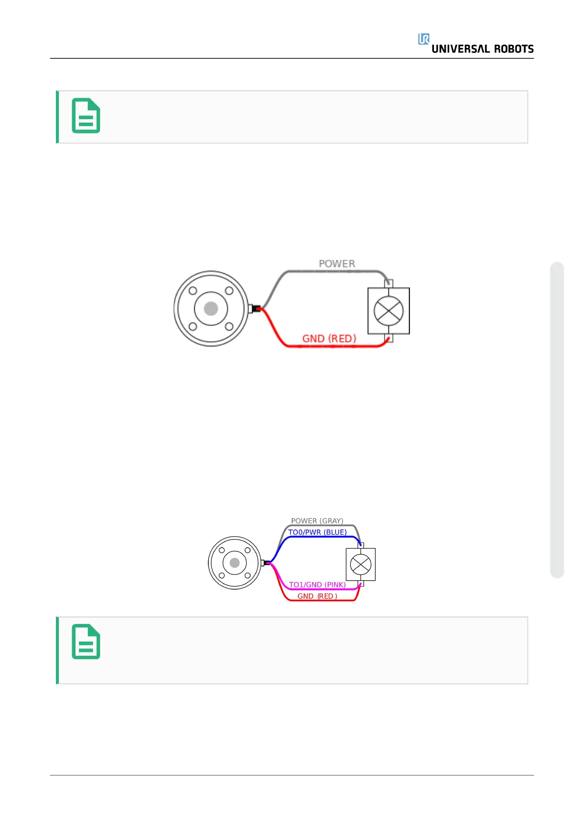
4.8.3. Dual Pin Power Supply
In Dual Pin Power mode, the output current can be increased as listed in (4.8. Tool I/Oon page45
table two).
1. In the Header, tap Installation.
2. In the list on the left, tap General.
3. Tap Tool IO and select Dual Pin Power.
4. Connect the wires Power (gray) to TO0 (blue) and Ground (red) to TO1 (pink).
NOTE
Once the robot makes an Emergency Stop, the voltage is set to 0V for both Power
Pins (power is off).
4.8.4. Tool Digital Outputs
Digital Outputs support three different modes:
Hardware Manual 47 UR5e
4.Electrical Interface
Copyright © 2009–2022 by UniversalRobotsA/S. All rights reserved.
 Loading...


