Mode Active Inactive
Sinking (NPN) Low Open
Sourcing (PNP) High Open
Push / Pull High Low
Access Tool I/O in the Installation Tab (see part) to configure the output mode of each pin. The
electrical specifications are shown below:
Parameter Min Typ Max Unit
Voltage when open -0.5 - 26 V
Voltage when sinking 1A - 0.08 0.09 V
Current when sourcing/sinking 0 1000 1000 mA
Current through GND 0 1000 3000* mA
*Peak for max 1 second, duty cycle max: 10%. Average current over 10 seconds must not exceed
typical current.
NOTE
Once the robot makes an Emergency Stop, the Digital Outputs (DO0 and DO1) are
deactivated (High Z).
CAUTION
The Digital Outputs in the tool are not current-limited. Overriding the specified data
can cause permanent damage.
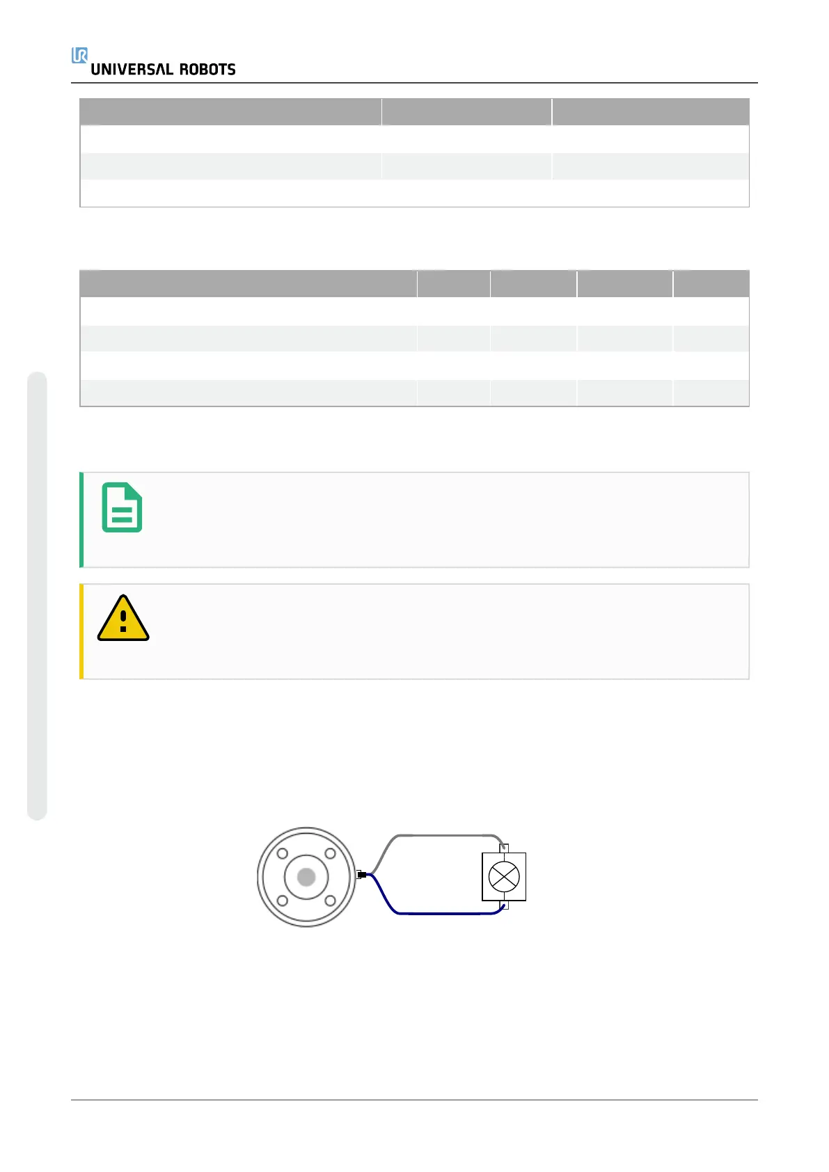
Using Tool Digital Outputs
This example illustrates turning on a load using the internal 12V or 24V power supply. The output
voltage at the I/O tab must be define. There is voltage between the POWER connection and the
shield/ground, even when the load is turned off.
It is recommended to use a protective diode for inductive loads, as shown below.
UR5e 48 Hardware Manual
4.Electrical Interface
Copyright © 2009–2022 by UniversalRobotsA/S. All rights reserved.
 Loading...


