MSC-400 Reference Manual
Rev 4
19
8 Relay +12V Normally Open 9 Relay +12V Normally Closed
NC (Normally Closed)
1. For a device that PROVIDES VOLTAGE for use with a switch closure:
a) Connect the +V TERMINAL on the CONTROLLED DEVICE to the RELAY 1 NC TERMINAL on
the MSC-400 REAR PANEL, using one of the included THREE-PIN PLUG-IN CONNECTORS.
b) Connect the GROUND TERMINAL on the CONTROLLED DEVICE to the RELAY 1 COM
TERMINAL using the same plug-in connector.
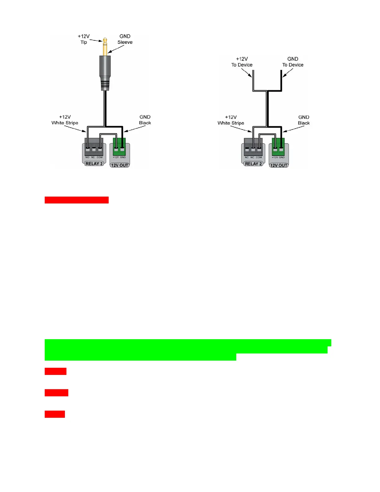
2. For a device that REQUIRES EXTERNAL CONTROL VOLTAGE:
a) Connect a JUMPER (24-14AWG two conductor stranded wire, typical) from the 12V OUT
TERMINAL on the MSC-400 REAR PANEL to the RELAY 1 COM TERMINAL as shown in 9
Normally Closed (Relay 2 Shown).
b) Connect the RELAY 1 NC TERMINAL to the +V TERMINAL on the CONTROLLED DEVICE.
c) Connect the GND TERMINAL on the CONTROLLED DEVICE to the GND TERMINAL on the
MSC-400 REAR PANEL as shown.
When a properly programmed MSC-400 compatible remote sends an ON COMMAND (latching, press
and hold or timed), RELAY 1 will OPEN and the controlled device will respond with an interruption to its
normal action. When the OFF COMMAND (latching, press and hold or timed) is sent, RELAY 1 will
CLOSE and the controlled device will respond by resuming its normal action. WIRE GAUGE: 24-14AWG
two-conductor stranded; MAX LOAD: 30V; .5A.
NOTE - Latching commands initiate an action until another command is sent. Press and hold and
timed commands perform the specified action only for as long as the button on a remote is held
(press and hold) or for the duration of the switch closure (timed).
Relay 2
1. Follow instructions as detailed in Relay 1 using the RELAY 2 TERMINALS.
12V Out
1. See Sections: CONNECTIONS RELAY 1/RELAY 2 above for use with the MSC-400 internal relays.
12VDC
1. Connect the included 12VDC 3.5A power supply after all system connections have been made and
confirmed. POLARITY: PIN=+12V; SLEEVE=GND