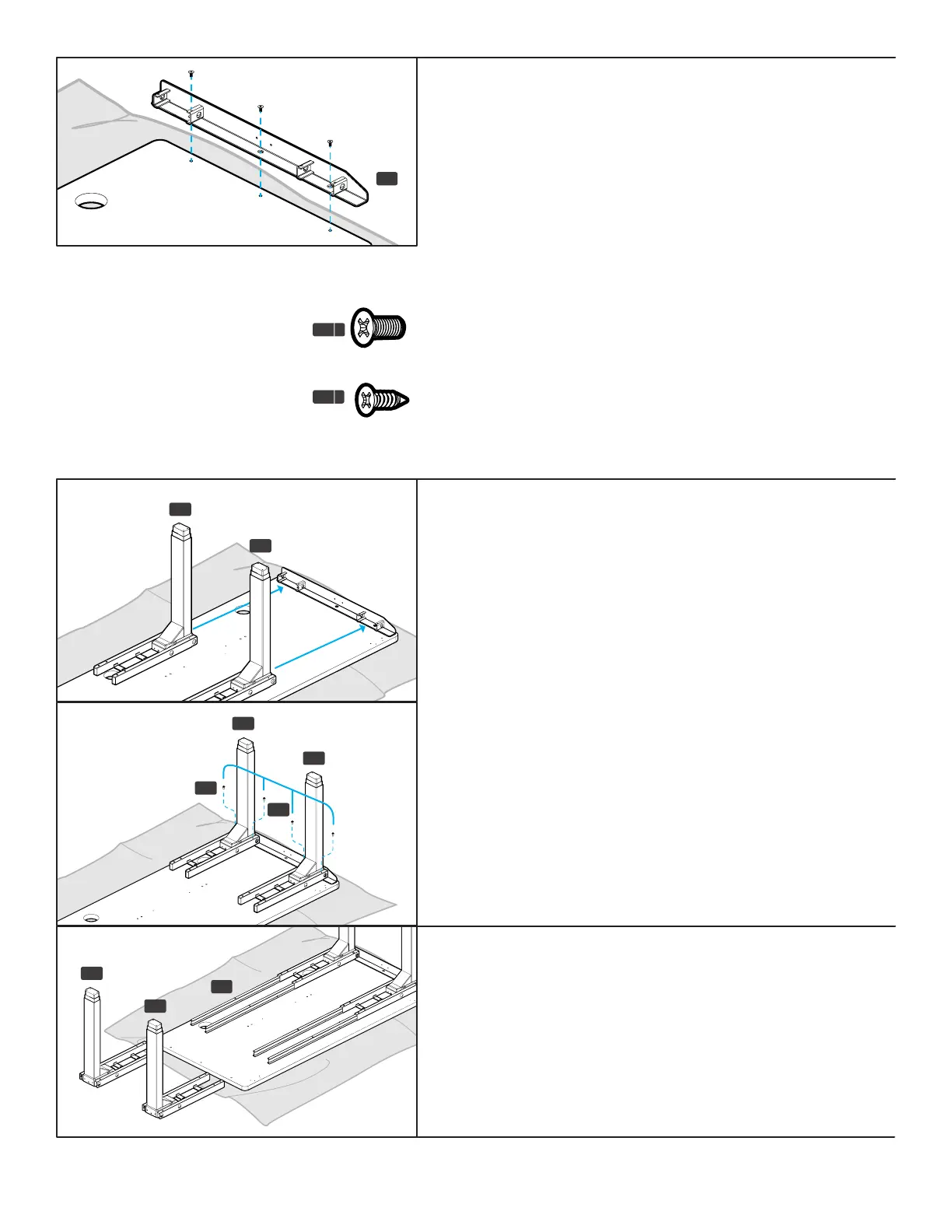
Step 6 - Leg Attachment (rst side)
A. Slide two Leg Assemblies (P1) from Step 2 onto the tabs of the
Side Bracket (P4) as shown.
B. Loosely insert two M6x10 Machine Screws (H1) through the top
of each Crossbar End (P2) and into the Side Bracket as shown.
Once all four screws have been started, tighten them using the
4 mm Allen Wrench (H6).
Step 7 - Crossbar Rail Installation
A. Insert two Crossbar Rails (P3) into each Crossbar End (P2) as
far as they will go.
B. Take the remaining leg assemblies (P1) and slide them onto
the Crossbar Rails as far as they will go.
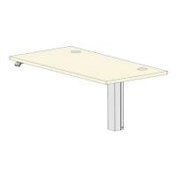
Step 5 - Side Bracket Attachment
(rst side)
A. Align the holes in the Side Bracket (P4) with the holes or
threaded metal inserts in the desktop. Note: Be sure that the
tapered end of the Side Bracket is pointing towards the front
of the desktop where the four Keypad attachment holes are
located.
IMPORTANT: Determine the correct screws to use based on
whether your desktop has threaded metal inserts or pre-drilled
holes.
• For desktops that have threaded metal inserts: use the
#10-24x5/8” Flat Head Machine Screws (H4c) for the
following steps. Do not use the wood screws with the pointy
end.
• For desktops that have pre-drilled holes: use the #10x5/8”
Flat Head Wood Screws (H4d) for the following steps.
B. Use a Phillips Head Screwdriver and the screws above to attach
the Side Bracket to the desktop.
P4
left
Machine screw: at end
H4
c
Wood screw: pointy end
H4
d
P3
P1
P1
P1
P1
P1
H1
H1
P1