Section 2 - Service and Repair Hydraulic Pump
113101-000 MX15 / MX19 | Service Manual Page 2-19
2-9 H
YDRAULIC
P
UMP
R
EMOVAL
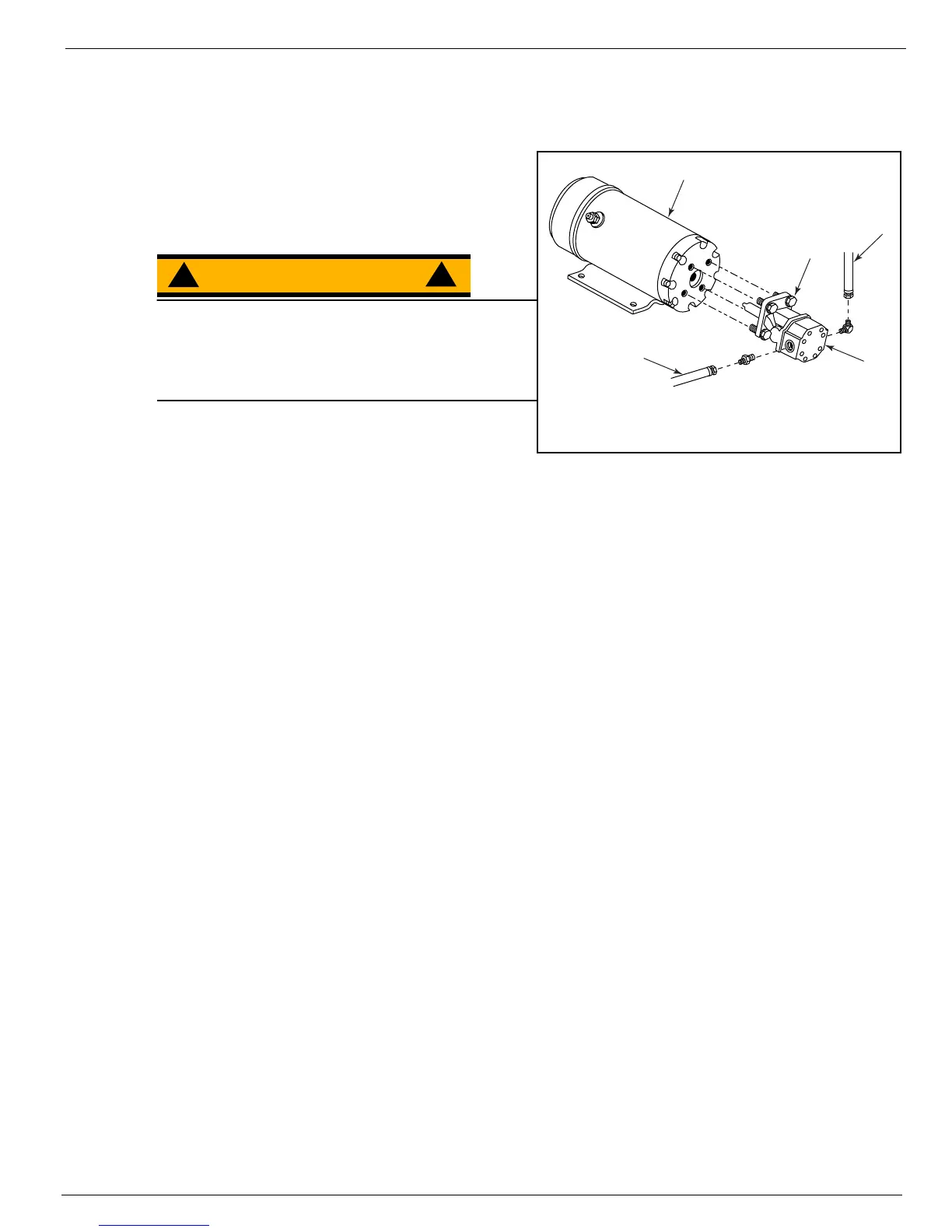
Figure 2-13:
Hydraulic Pump
NOTE:
If the hydraulic reservoir has not been drained,
suitable means for plugging hoses should be provided
to prevent excessive fluid loss.
WARNING
!
!
Before disconnecting the battery negative (–) lead,
make sure all switches are OFF. If ON, a spark will
occur at the ground terminal which could cause an
explosion if hydrogen gas or fuel vapors are
present.
1. Open the right door and disconnect the battery
connector.
2. Open the left door and disconnect the negative (–) lead on the number 1 battery.
3. Mark, disconnect and plug the hose assemblies.
NOTE:
It may not be necessary to remove the motor to service or remove the pump.
4. Disconnect the power supply from the motor.
5. Remove the four cap screws from the vibration mounts and lift the motor and pump assembly.
6. Loosen the capscrews and remove the pump assembly from the motor.
I
NSTALLATION
Pump to Motor
1. Lubricate the pump shaft with general purpose grease and attach the motor with the capscrews.
2. Using a crisscross pattern, torque each capscrew a little at a time until all capscrews are torqued to
27 N-m (20 ft./lbs.).
Pump and Motor Assembly to Chassis
3. Position the motor and vibration mounts into the chassis.
4. Put a drop of Loctite® 242 thread lock on each capscrew as you install the capscrew and lock washer.
5. Tighten the motor mount nuts to 24 N-m (18 ft./lbs.).
6. Unplug and connect the hydraulic hoses.
7. Connect the power supply to the motor.
8. Connect the battery negative (–) lead.
9. Connect the battery pack connector.
10. Check the fluid level in the hydraulic reservoir before operating the machine.
1
2
3
5
4
1. Inlet Hose
2. Outlet Hose
3. Capscrew
4. Pump Assembly
5. Electric Motor