Hydraulic Drive Motors Section 2 - Service and Repair
Page 2-20 113101-000 MX15 / MX19 | Service Manual
2-10 H
YDRAULIC
D
RIVE
M
OTORS
D
RIVE
M
OTORS
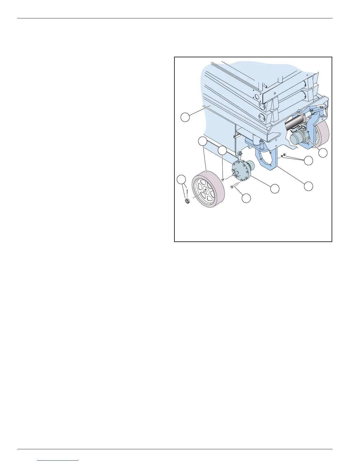
Figure 2-14:
Drive Motor
R
EMOVAL
1. Chock the rear wheels to prevent the
machine from rolling.
• Use a 1000 Kg (1 ton) capacity jack to
raise the front of the machine.
• Place two 1000 Kg (1 ton) jackstands
beneath the machine for support.
• Remove the jack.
2. Remove the cotter pin and slotted nut.
3. Remove the wheel.
NOTE:
It may be necessary to use a wheel puller to
remove the wheel.
4. Remove the shaft key.
IMPORTANT: Before disconnecting any hoses,
thoroughly clean off all the outside dirt around
the fittings. IMMEDIATELY plug the holes after
disconnecting the hoses and before removing
the motor from the machine.
5. Tag, disconnect and plug the hose
assemblies to prevent foreign material
from entering.
6. Remove the locknuts, washers and capscrews.
7. Remove the drive motor.
I
NSTALLATION
1. Position the drive motor into the wheel yoke and secure it with capscrews and locknuts.
2. Torque the locknuts to 95 N-m (70 ft./lbs.).
3. Remove the plugs from the hose assemblies and connect them to the drive motor.
4. Clean the motor shaft and hub bore and lubricate the slotted nut face and threads.
5. Install the shaft key, wheel, and slotted nut. Torque the slotted nut to 95-108 N-m (70-80 ft./lbs.).
6. Install a new cotter pin. DO NOT back-off the nut to install the cotter pin.
7. Remove the jackstands and lower the machine to the ground.
8. Check the fluid level in the hydraulic reservoir before operating the machine.
9. Operate the drive system and check for leaks.
8
7
5
4
1
3
6
6
2
1. Chassis
2. Cotter Pin and Slotted Nut
3. Wheel
4. Shaft Key
5. Hydraulic Hoses
6. Locknuts, Washers and
Capscrews
7. Drive Motor
8. Wheel Yoke