Depression Mechanism Cylinder Section 2 - Service and Repair
Page 2-24 113101-000 MX15 / MX19 | Service Manual
2-12 D
EPRESSION
M
ECHANISM
C
YLINDER
R
EMOVAL
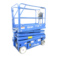
Figure 2-19:
Depression Mechanism Cylinder
1. Open the module door to access
the cylinder.
2. Tag and disconnect the hose
assemblies from the cylinder fit-
tings and immediately cap the
openings to prevent foreign
material from entering.
3. Remove the cotter rue ring from
the upper pivot pin.
4. Remove the cotter pin from the
lower pivot pin.
5. While supporting the cylinder,
remove pivot pins and lift the cyl-
inder out.
R
EPAIR
Refer to
Section 1 - General Infor-
mation
for disassembly, cleaning
and inspection, and assembly
instructions.
I
NSTALLATION
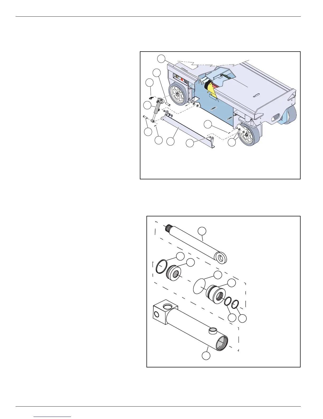
Figure 2-20:
Depression Mechanism Cylinder
1. Position the cylinder assembly in
the chassis. Insert the pivot pins
and secure with new cotter pins.
2. Connect the hose assemblies to
the fittings.
3. Operate the steering circuit several
times throughout its entire range of
travel to expel trapped air, then
check for leaks.
2
6
7
3
8
7
9
5
4
1
1. Depression Cylinder Mount
2. Depression Cylinder
3. Depression Rail
4. Upper Pivot Pin
5. Cotter Rue Ring
6. Lower Pivot Pin
7. Cotter Pin
8. Bearing
9. Flat Washers
A
D
1
3
2
4
B
C
A. Rod
B. Head
C. Piston
D. Tube
Seal Kit Includes:
Description Qty
1. Seal 1
2. O-Ring 1
3. Seal 1
4. Wiper 1