Page 3-17
Maintenance 3.14 - Brake Cylinder
MX15/19
I
NSTALLATION
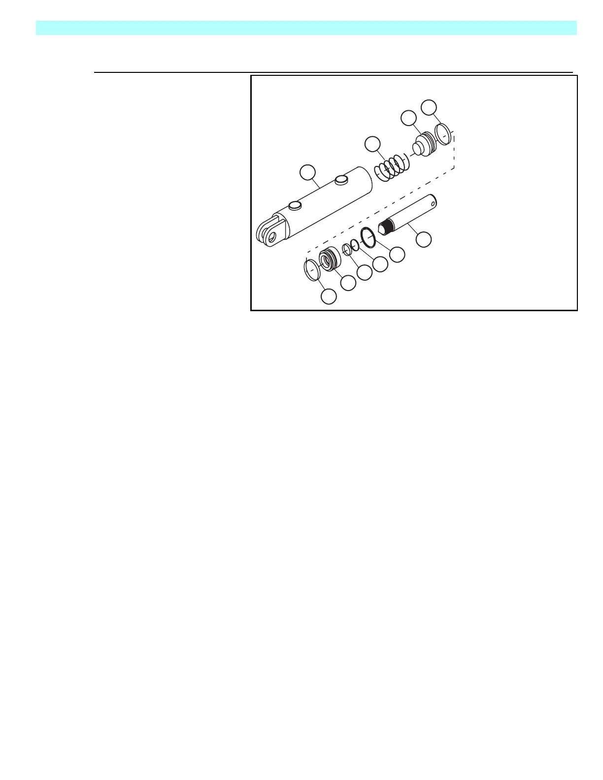
Figure 3-20:
Brake Cylinder Assembly
1. Install the cle-
vis end pivot
pin through the
cylinder clevis
and cylinder
link and secure
withanewcot-
ter pin.
2. Install the rod
end shoulder
bolt through
the cylinderrod
and brake tube
mounting tabs,
and secure
with the lock-
nut.
3. Install the
hydraulic
hoses.
4. Install the adjustment bolt and locknut. Tighten the bolt until the brakes have fully engaged
the tires. Secure the bolt with the locknut.
5. Lower the machine and operate the drive circuit to check that the brakes retract and clear the
tires when driving and fully engage the tires when stopped. Verify that the brakes fully
engage the rear tires by testing their ability to hold the machine on a 25% (14°) grade. If they
do not, tighten the adjustment bolt until they do. Secure the bolt with the locknut.
6. Check for leaks.
A. Cylinder
B. Piston
C. Head
D. Rod
Description
1. Spring
2. Seal
3. Seal
4. Wiper
5. Snap Ring
Seal Kit Includes:
Qty
1
2
1
1
1
A
B
C
D
1
2
3
4
5
Seal Kit Part Number
066604-010
2