23
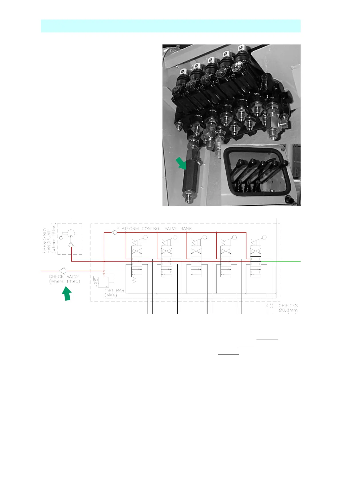
CONTROL VALVE - CAGE
Is shown on the diagram below with the
manual hand pump on the left hand side.
Below the handpump is the inline check
valve which prevents the oil going back
down the pressure line when operating
the hand pump.
The relief valve shown here is set at 190
Bar and should be adjusted in
accordance with the setting up procedure.
Shown elsewhere, see section :
The relief valve can be seen on the
picture insert in the bottom right hand
corner. Remove cap and screw adjusting
screw in to increase pressure and out to
decrease pressure. Put cap back after
adjusting
The spools are all the same. They are all closed centre in the neutral position. It is critical
that the valve block does not leak internally when in the neutral position. Remember you
have two valve blocks. Each is connected together at the lift cylinders. If the Ground
valve is
not leak free, with the spool in the neutral position, when operating the Cage
valve, the oil will
not go into the cylinder but leak out (internally) through the Ground
valve. This can also
happen if the spool is not properly centralised by the spring at the end of the spool.
The same thing is true if you operate the Ground controls and the Cage valve is leaking
internally.
The normal symptom for this problem is when the operator reports that “everything works
fine from the ground controls but when operating from the cage, boom x does not move.
Motor runs but nothing happens.” In this case the valve which makes the boom work
correctly is in fact the valve which is at fault!
MAINTENANCE PROCEDURE