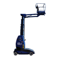
Page 3-1TL38 Service & Parts
Section 3
MAINTENANCE
3.1 INTRODUCTION
NOTE: For Information on the engine refer to your local engine dealer.
This section contains instructions for the maintenance of the Work Platform. Procedures for the
operation, inspection, adjustment, scheduled maintenance, and repair/removal are included.
Referring to Section 2 will aid in understanding the operation and function of the various compo-
nents and systems of the work platform, and help in diagnosing and repair of the machine.
TERMINOLOGY
TERMINAL BLOCKS Located in upper and lower control boxes. Designated by TB##. (##) designates the number of the
block which is written on the terminal block. “R” (right) or “L” (left) may follow the number.
WIRE COLOR Indicated by color/color. First color refers to insulation color and second color indicates stripe. If sec-
ond color is not given, there is no stripe.
GENERAL PROCEDURES
CONTACT BLOCKS Removed by inserting a flat screwdriver into the slot at either end of block and prying outward.
Installed by pressing into an empty slot.
SWITCH MOUNT
BASE
Assembled to back of switch actuator. Removed by rotating the small black lever counterclockwise
and lifting off base.
TERMINAL BLOCKS Remove wires by inserting a small flat bladed screwdriver into square beside wire. Install wires by
stripping ½” of insulation, inserting screwdriver in square and inserting wire. Be sure no strands are
bend backwards. Replace wires with same rating and type.
WARNING
!
!
Be sure to read, understand and follow all information in the Operation
Section of this manual before attempting to operate or perform service on
any work platform.