Page 3-6
Maintenance 3.5 - Switch Adjustments
TL38 Service & Parts
3.5 SWITCH ADJUSTMENTS
TILT SENSOR
INTRODUCTION
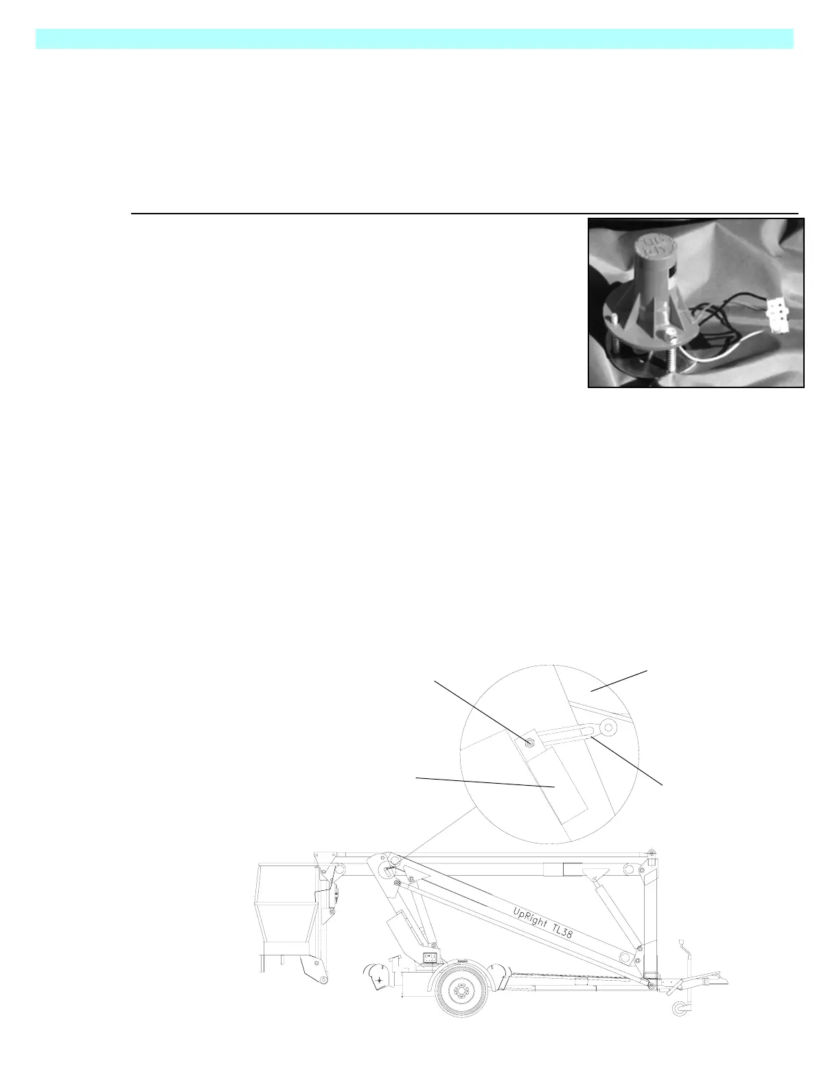
The Tilt Sensor Is located on the right hand side of the chassis above the axle, It has three wires;
red-power (24 v in), black-ground, white-output (24 v out). To verify the sensor is working prop-
erly there is one LED under the sensor that indicates the sensor is off level.
Figure 3-2: Level Sensor
ADJUSTMENT
1. Place the machine on a firm, level surface ± 1/4°.
2. Use the Inclinometer (P/N: 10119-000-00) to ensure
the front and rear of the Chassis is level ± 1/4°.
3. Adjust the three leveling locknuts until the bubble is
centered in the circle on the attached bubble level.
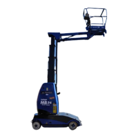
SLEW CUT-OUT LIMIT SWITCH
Function: The purpose of this limit switch is to prevent the operator from slewing while the lower
boom and second post are on or near the towbar thus preventing accidental damage to it. It does
this by breaking the slew signal from the upper or lower controls while the second post is less
than approximately 1 m above the ground.
Location: The switch is located on the first post boom pivot plate.
Adjustment: To adjust the switch loosen the lever clamping nut and rotate the lever. Tighten the
lever clamping nut. The lever is actuated by the lower boom. as it descends.The Normally
Closed contacts of the switch should open when the lower boom is at an angle such that the bot-
tom of the second post is approx. 1 m above the ground.
Lever Clamping Nut
Switch Body
Switch Lever
Lower Boom