Page 1-1TL38 Service & Parts
Section 1
INTRODUCTION
1.1 INTRODUCTION
PURPOSE
The purpose of this service and parts manual is to provide instructions and illustrations for the
operation and maintenance of this work platform manufactured by UpRight.
SCOPE
The manual includes procedures for proper operation, maintenance, adjustment, and repair of
this product as well as recommended maintenance schedules and troubleshooting.
1.2 GENERAL DESCRIPTION
The work platform consists of the platform, controller, elevating assembly, power & control mod-
ule, and chassis.
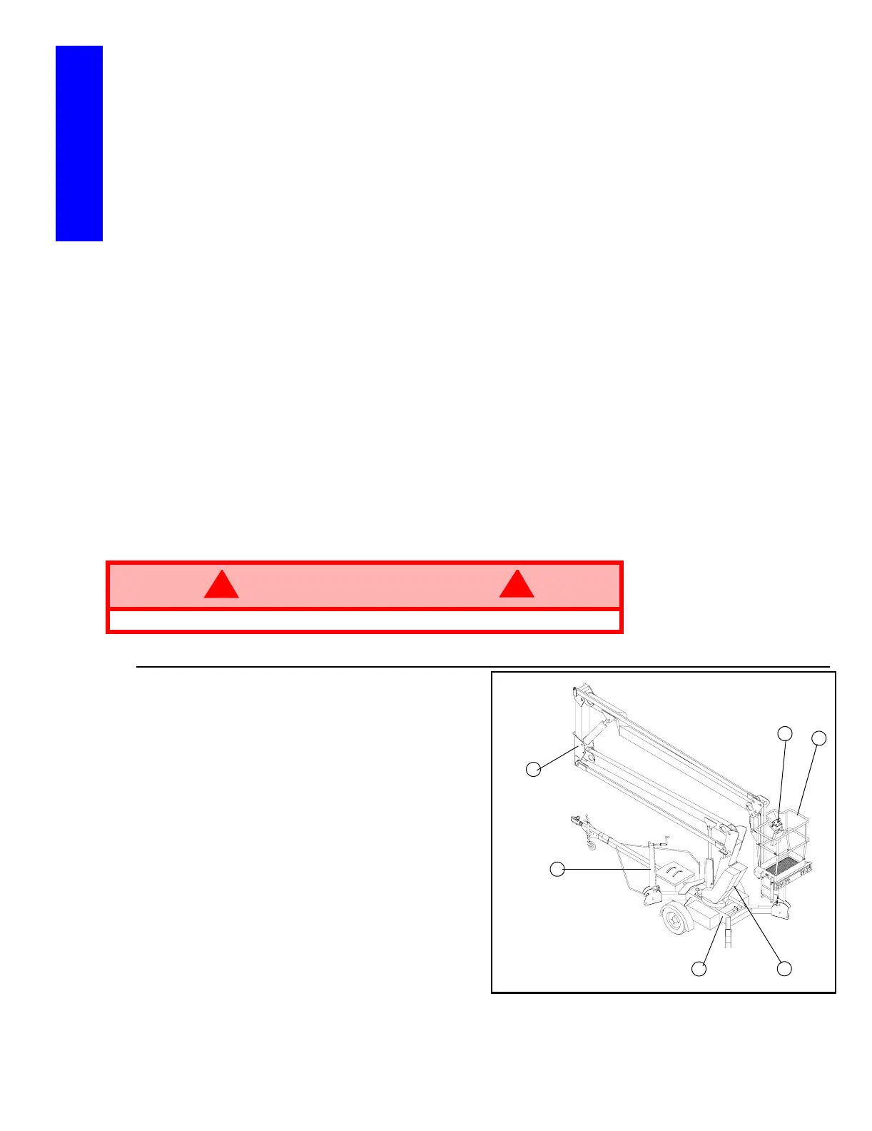
Figure 1-1: TL38 Work Platform
PLATFORM
The platform has a reinforced steel
floor, 1.1m (43.5 inch) high guardrails
with midrail, 152 mm (6 inch ) toe-
boards, and an entry gravity drop bar at
the side of the platform.
PLATFORM CONTROLLER
The platform controller contains the
controls to operate the machine. It is
located at the front of the platform cage.
A complete explanation of control func-
tions can be found in Section 2.
ELEVATING ASSEMBLY
The platform is raised and lowered by
the elevating assembly. The hydraulic
pump, driven by batteries powers the
cylinders. Solenoid operated valves
control raising and lowering.
CHASSIS
The chassis is a structural frame that supports all the components of the TL38 work platform.
WARNING
!
!
DO NOT use the work platform without gravity drop bar in position.
1.Platform
2.Platform Controller
3.Chassis Controls
4.Chassis
5.Elevating Assembly
6.Outriggers
1
2
3
4
5
6