OPERATING PRINCIPLE
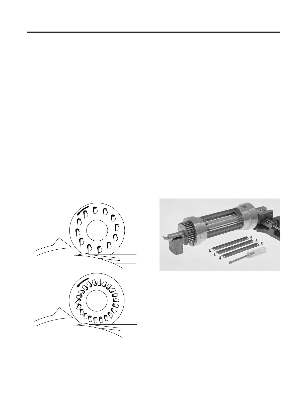
There are two types of crosscut knife spindle
designs. The 7, 8, 10, 12, 14 and 16 knife spin-
dles use an eccentric to maintain the “edge-
down” position of the knives as they rotate past
one another and around the spindle (Figure
36). This design limits the number of knives
that can be placed on the spindle.
The 22 knife spindle (used for 9/32" cuts)
overcomes this limitation by using a cam to
keep the knife edges facing outward as the
spindle rotates.
NOTE: Inspection information and re-
assembly procedures are different for the two
types of spindle.
DISASSEMBLY (all spindles)
1. Remove crosscut knife spindle from dic-
ing unit. See “Disassembly”, page 36.
2. Remove knife screws and knives. Place
spindle in “V” block support which will allow
spindle to turn but prevent it from rolling
(Figure 37). Use the hex driver to remove
knife screws. (At this point the idler pins
should be removed from the 22 knife spin-
dle.)
3. Clamp spindle in soft jaw vise onto cen-
tral spool with gear side down.
4. Remove grease fittings from shaft. A pin
held in locating hole of shaft will prevent
shaft from turning.
40
MAINTENANCE
Crosscut Knife Spindle Assembly
Figure 36 — Knife orientation on the two different spin-
dle designs. “Knife edge down” in 7, 8, 10, 12, 14 & 16
knife spindles (top). “Knife edge out” in 22 knife spindle
(bottom).
Figure 37 — Removing crosscut knives.
 Loading...