EasyManua.ls Logo

Urschel G-A - Page 93

Urschel G-A
174 pages
Print Icon
To Next Page IconTo Next Page
To Previous Page IconTo Previous Page
Loading...
OPERATION
Safety Switches
23
RELAY
CONDITION
C
2
LOGIC AMPLIFIER
FYQLA1-140R-3
D
E
S
O
L
N
E
P
O
117 V
6
OBWR
5
OBWR
4
OBWR
3
OBWROBWRO
.315 A
R2R1L2L1
RW B
1
1
2
3
4
5
6
9
12
11
7
8
10
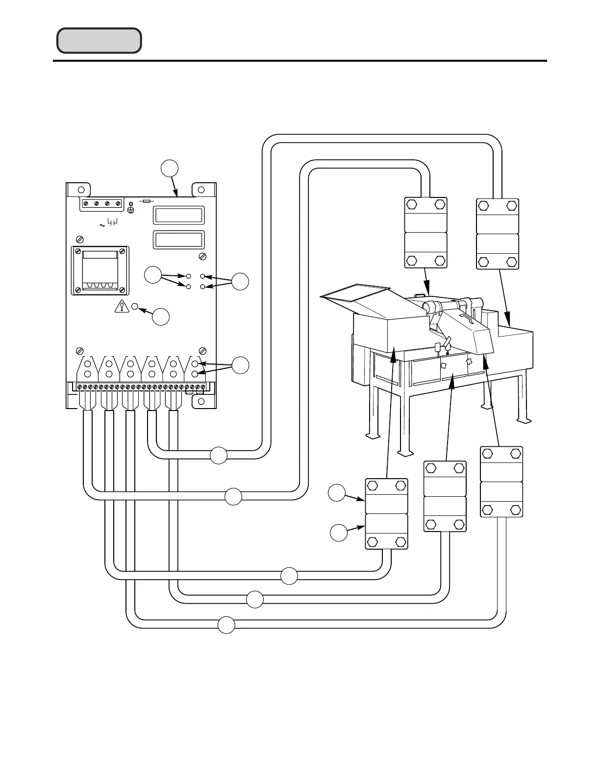
Figure 18 — Amplifier and safety switches with corresponding covers and guards (1) Chip Chute Enclosure, (2)
Feed Hopper, (3) Discharge Chute, (4) Motor Cover, (5) Side Cover, (6) Amplifier, (7) Green “Relay Condition”
LEDs, (8) Red “Relay Condition” LEDs, (9) Red “Attention” LED, (10) Red “Switch Output” LEDs, (11) Sensor,
(12) Actuator.
See the addendum
for updated information

Table of Contents