USR-TCP232-T2 user manual www.usriot.com
Jinan USR IOT Technology Limited www.usriot.com
3. Hardware parameter
3.1. Pin define
3.1.1. Pin Definition
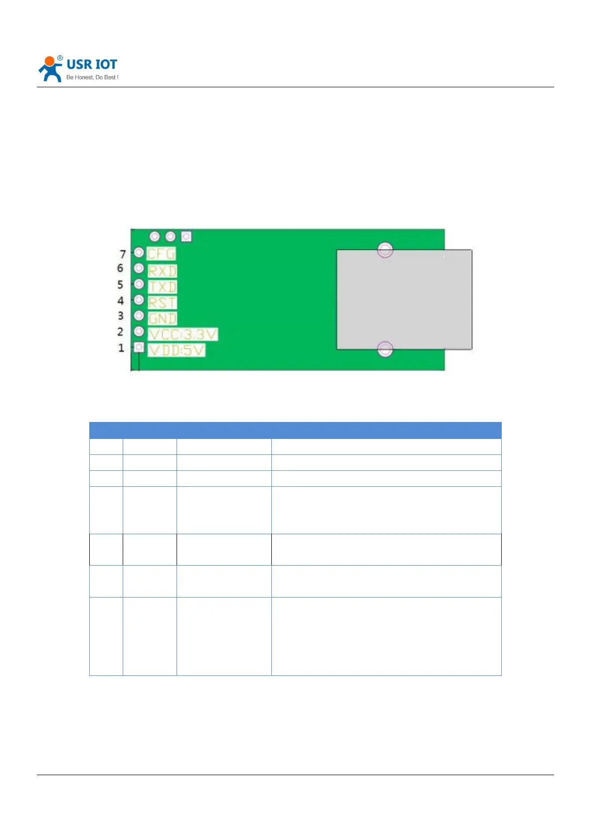
Diagram 3.1.1-1 T2 Interface Definition
Pin receive current below 200ms ,it can reset
module. If unneeded, don’t connect the pin .
(Power on , reset means restart the module)
TTL connect to 3.3v MCU
(For 5V, refer to Diagram 3.1.1-2)
TTL connect to 3.3v MUC
(For 5V, refer to Diagram 3.1.1-2)
Pin for module
configuration and
restore
factory default
When normal working , don’t connect the pin or
connect to high level. Under low level, the pin is
used for module configuration, access to power
then pull down“Reload” pin
Refer to 4.4.3 Factory Reset
Form 3.1.1-1 T2 Pin Definition