

K
Kelly SmithSep 12, 2025
How to fix Flue NTC heat exchanger sensor fault in UTICA BOILERS Boiler?
- SSusan HutchinsonSep 12, 2025
If your UTICA BOILERS Boiler displays a Flue NTC heat exchanger sensor fault, check the sensor and its cable.
How to fix Flue NTC heat exchanger sensor fault in UTICA BOILERS Boiler?
If your UTICA BOILERS Boiler displays a Flue NTC heat exchanger sensor fault, check the sensor and its cable.
How to troubleshoot Return NTC sensor fault in UTICA BOILERS Boiler?
If your UTICA BOILERS Boiler displays a Return NTC sensor fault, check the sensor and its cable.
What to do if UTICA BOILERS Boiler shows Domestic Hot Water NTC sensor fault?
If your UTICA BOILERS Boiler displays a Domestic Hot Water NTC sensor fault, check the sensor and its cable.
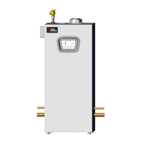
Details of boiler dimensions including height, width, depth, and connections.
Describes Central Heating (Sealed System) and Domestic Hot Water system configurations.
Provides essential safety warnings and precautions for boiler operation and installation.
Details installation compliance with national, local codes, and Massachusetts requirements.
Describes boiler's intended use, limitations, and key operational features.
Lists and illustrates components specific to the MAH-100 model.
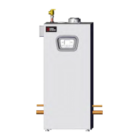
Lists and illustrates components specific to the MAH-125 model.
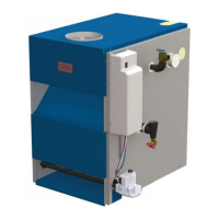
Lists and illustrates components specific to the MAH-165 model.
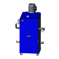
Lists and illustrates components specific to the MAC-115 model.
Lists and illustrates components specific to the MAC-150 model.
Lists and illustrates components specific to the MAC-205 model.
Guidance on selecting an appropriate and safe location for boiler installation.
Details service and combustible clearances required around the boiler.
Step-by-step instructions for mounting the boiler on a wall.
General requirements for combustion air and vent piping installation.
Details on installing coaxial venting systems, including measurements and safety.
Explains different twin pipe venting configurations and installation requirements.
Instructions for installing the condensate drain system, including material and slope requirements.
General guidelines for hydronic piping installation and system requirements.
Details on installing and maintaining the safety relief valve and air vent.
Information on system piping configurations and additional considerations for single boiler systems.
Guidelines for installing an optional low water cutoff device for boiler protection.
Details on the boiler's design for sealed central heating systems and components.
General requirements for gas supply piping installation and materials.
Guidelines for configuring gas piping for optimal operation and avoiding issues.
Procedure for leak testing gas piping and connections before boiler operation.
General electrical bonding and wiring requirements for the boiler.
Instructions for accessing the boiler's terminal blocks for wiring connections.
Instructions for connecting optional accessories like outdoor temperature sensors.
Details on electrically connecting the boiler to an indirect storage tank.
Illustrates piping connections for heat-only models, with and without indirect DHW.
Step-by-step procedure for initiating system operation and purging air.
Overview of the boiler's control panel, buttons, and symbols for operation.
Procedure for initial boiler setup, including gas type identification and calibration.
Detailed steps for manual calibration of combustion parameters.
Procedure to enable maximum heating power and adjust boiler settings.
Guide to programming and adjusting boiler electronic board parameters.
Guidance on reducing maximum boiler heating power to suit system requirements.
Procedure for checking gas leaks and purging the gas supply system.
Explanation of the boiler's frost protection feature and its operation.
Checks and procedures to perform at the start of each heating season for safe operation.
Routine checks and servicing frequency recommendations for peak boiler efficiency.
Instructions for safely draining water from the boiler.
Steps to balance the system and check for proper volume and pressure after heating.
Information to be advised and demonstrated to the user regarding boiler operation and maintenance.
Presents technical data including input, capacity, and AHRI ratings for various boiler models.
Details on how altitude affects boiler performance and ratings.
Lists error codes and initial checks for diagnosing boiler faults.
Flowcharts for diagnosing and resolving issues with central heating and domestic hot water.
Detailed troubleshooting steps for specific error codes and system faults.
Definitions of technical terms used throughout the manual for clarity and understanding.
Wiring diagram for the Model 100 Heat Only boiler.
Wiring diagram for the Model 125 Heat Only boiler.
Wiring diagram for the Model 165 Heat Only boiler.
Wiring diagram for the Model 115 Combi boiler.
Wiring diagram for the Model 150 Combi boiler.
Wiring diagram for the Model 205 Combi boiler.
Explains safety alert symbols used in the manual to indicate potential hazards.
Piping diagrams for 100/125 models with and without indirect DHW.
Piping diagrams for 165 models, including manifold details.
Piping installation, materials, and joining methods must conform to authority requirements.
Guidance on connecting an indirect water heater to heating-only boilers.
Field wiring must conform to authority having jurisdiction and electrical codes.
Key to symbols used in piping diagrams for component identification.
Diagram showing buffer tank connection using internal boiler circulator.
Wiring diagram for buffer tank pump control on a combi boiler with zone valves.
Details on the 1k Ohm Outdoor Air Sensor, including connection and climate curve settings.
Information about the 1k Ohm Outdoor Temperature Sensor Kit, including installation and settings.
Details on the 10k Ohm sensor for indirect DHW tanks and 0-10V input management.
Wiring diagram for single zone circulator using ARGO AR822-II control.
Guidelines for installing an additional Low Water Cut Off (LWCO) for boiler protection.
Diagram illustrating the wiring connections for the Low Water Cutoff device.
Diagram illustrating the correct placement of the LWCO in the piping system.
Illustrations showing correct and incorrect installation positions for the LWCO sensing element.
Lists error codes and initial checks for diagnosing boiler faults.
Troubleshooting flowchart for issues related to the central heating operation.
Troubleshooting flowchart for issues related to domestic hot water operation.
Troubleshooting steps for power supply and PCB related faults.
Troubleshooting steps for sensor faults and their related issues.
Troubleshooting steps for overheat thermostat and system pressure issues.
Troubleshooting steps for water filter and PCB issues.
| Model | MAC-150 |
|---|---|
| Category | Boiler |
| Type | Hot Water Boiler |
| Fuel Type | Natural Gas or Propane |
| Input BTU/hr | 150, 000 |
| Efficiency | 95% |
| AFUE | 95% |
| Vent Diameter | 2 or 3 inches |