NOT ALL COMPONENTS LISTED ARE USED IN ALL CONTROL SYSTEMS.
4. Honeywell hot water control and hot surface ignition wiring for USC series boilers.
See figure 9 on page 9.
NOTES:
• Switches are shown in position during the heating cycle.
• If any of the original wiring supplied with the boiler is replaced it must be
replaced with like wire size and type of insulation or equivalent.
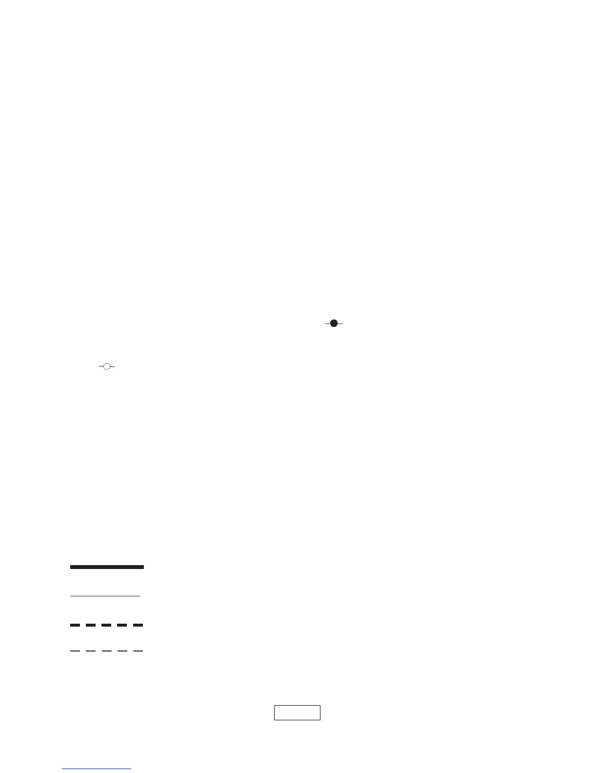
5. WIRING CODE
LINE VOLTAGE BY FACTORY
LOW VOLTAGE BY FACTORY
LINE VOLTAGE BY INSTALLER
LOW VOLTAGE BY INSTALLER
1K2 Relay Contacts
LS Limit Switch
MS Manual Switch
CIR Circulator
ECO Energy Cut-Off
PSC Pilot Safety Coil
Wire Connection
LWCO Low Water Cut Off
EWF Electric Water Feeder
PG Power Generator
RSW Roll-Out Switch
TH-1 Thermostat (millivolt)
TH-2 Thermostat (24 Volt)
TH-3 Thermostat (Line Voltage)
TR-1 Transformer (120V/24V 40VA)
TR-2 Transformer (120V/24V 50VA)
LGV 24 Volt Gas Valve
LGV-1 24 Volt Gas Valve
PS Pressure Switch
MR-PS Manual Reset Pressure Sw.
Control Terminal
1K Relay Coil
1K1 Relay Contacts
ELECTRICAL WIRINGELECTRICAL WIRING
ELECTRICAL WIRINGELECTRICAL WIRING
ELECTRICAL WIRING
Electrical wiring must conform with National Electrical Code, ANSI/NFPA No. 70 when
installed in the United States, the CSA C22.1 Canadian Electrical Code, Part 1, when
installed in Canada, and/or the local authority having jurisdiction.
1. When an external electrical source is utilized, the boiler, when installed, MUST BE
electrically grounded in accordance with these requirements.
2. Install a fused disconnect switch between boiler and meter at a convenient location.
PAGE 8
3. COMPONENT CODING (SEE WIRING DIAGRAM ON PAGE 9)