INSTINST
INSTINST
INST
ALLAALLA
ALLAALLA
ALLA
TION PRTION PR
TION PRTION PR
TION PR
OCEDUREOCEDURE
OCEDUREOCEDURE
OCEDURE
WARNING: Improper installation, adjustment, alteration, service or
maintenance can cause injury or property damage.
1. The installation must conform to the requirements of the authority having jurisdiction or,
in absence of such requirements to one of the following:
When installed in the United States: The latest revision of the National Fuel Gas
Code, ANSI Z223.1. (Available from the American Gas Association, Pleasant Valley
Road, Cleveland, Ohio 44134.) Reference should also be made to local gas utility
regulations and other codes in effect in the area in which the installation is to be made.
When installed in Canada: The latest revision of the CAN1-B149.1 and/or B149.2
Installation Codes for Gas-Burning Equipment and/or local codes.
2. Where required by the authority having jurisdiction, the installation must conform to
American Society of Mechanical Engineers Safety Code for Controls and Safety
Devices for Automatically Fired Boilers, ANSI/ASME No. CSD-1.
3. This boiler is classified as a Direct Vent and vent installation shall be in accordance with
Part 7 of the latest revision of the National Fuel Gas Code, ANSI Z223.1 when installed
in the United States. In Canada refer to the CAN1-B149.1 and/or B149.2 Installation
Codes for Gas-Burning Equipment. Also refer to applicable provisions of the local
building codes.
4. LOCATE BOILER on level, solid base as near the outside wall as possible and centrally
located with respect to the heat distribution system as practicable.
5. 24 inches (61 cm) of clearance is recommended at the front and right side for servicing
and cleaning.
6. When installed in utility room, the door should be wide enough to allow the largest boiler
part to enter, or to permit replacement of another appliance such as a water heater.
7. The boiler shall be installed such that the gas ignition system components are protected
from water (dripping, spraying, rain, etc.)
during appliance operation and service,
(circulator replacement, condensate trap,
control replacement, etc.).
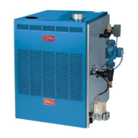
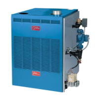
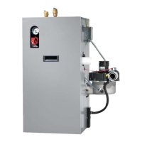
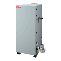
8. THIS BOILER IS DESIGN CERTIFIED
FOR INSTALLATION ON NON-
COMBUSTIBLE FLOORS ONLY. FOR
INSTALLATION ON COMBUSTIBLE
FLOORING SPECIAL BASE PART
NUMBER 325-2-8.00 MUST BE USED.
The boiler must NEVER be installed on
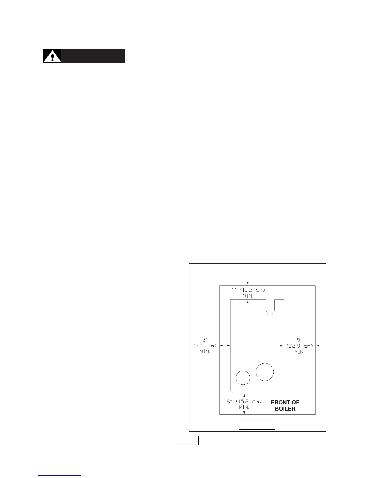
carpeting. Minimum clearances to
combustible constructions are:
TOP.................................... 18 IN. (46 cm)
FLUE CONNECTOR .............. 2 IN. (5 cm)
FRONT ................................. 6 IN. (15 cm)
REAR ................................... 4 IN. (10 cm)
RIGHT SIDE......................... 9 IN. (23 cm)
LEFT SIDE ............................. 3 IN. (8 cm)
(SEE FIGURE 1 AT RIGHT)
NOTE : GREATER CLEARANCES FOR
ACCESS SHOULD SUPERSEDE FIRE
PROTECTION CLEARANCE.
PAGE 2
FIGURE 1
CLEARANCE TO COMBUSTIBLE MATERIAL