CHECK CHECK
CHECK CHECK
CHECK
VENTER STVENTER ST
VENTER STVENTER ST
VENTER ST
AA
AA
A
TIC PRESSURE TIC PRESSURE
TIC PRESSURE TIC PRESSURE
TIC PRESSURE
AS FOLLAS FOLL
AS FOLLAS FOLL
AS FOLL
OO
OO
O
WS:WS:
WS:WS:
WS:
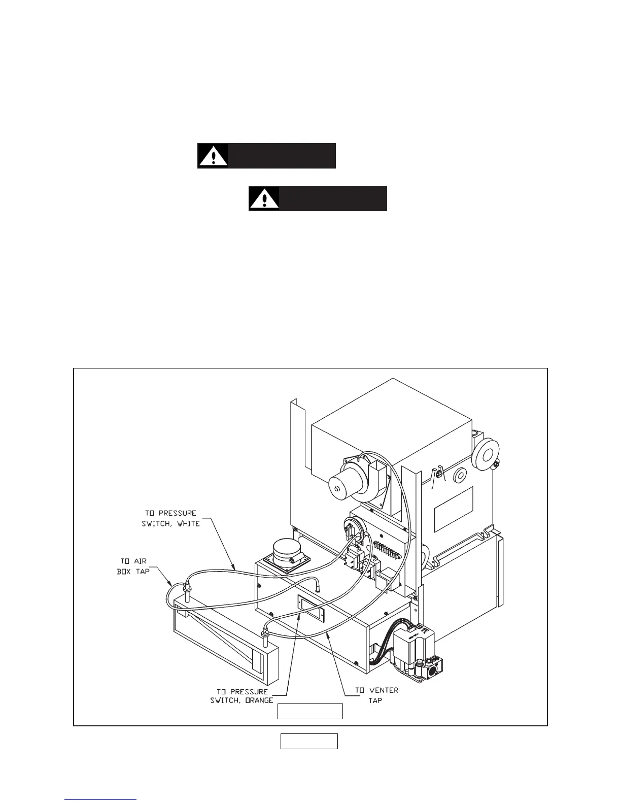
(Refer to figure 18 below for the following instructions.)
1. With the boiler off, disconnect the orange and white tubings from the pressure switch
on the air box and venter motor.
2. Install a 3/16" (.48 cm) plastic barbed tee between a slope manometer and the
pressure switch. (
CAUTIONCAUTION
CAUTIONCAUTION
CAUTION
::
::
: Do not cut original tubing.
Additional tubing is required.) If the tubing is cut, replace it only with O.E.M. high
temperature silicone tubing.
CAUTIONCAUTION
CAUTIONCAUTION
CAUTION
::
::
:
Do not replace with vinyl
or plastic tubing because it will melt.
3. The other part of the tee goes to the air box and venter pressure taps.
A. Orange being the high negative.
B. White being the low negative.
4. Turn the boiler back on and read the static pressure. The reading should be -
.55±.05 inches water column or higher for the USC series boilers.
5. If the static pressures are not at the minimum allowable level, check the intake and
exhaust pipes for obstructions or damage.
6. To reassemble, remove the tees and additional tubing and replace the orange tube
to the venter tap, and the white tube to the air box tap.
PAGE 16
FIGURE 18