15
Lowes.com
®
INSTALLATION INSTRUCTIONS
4
5
Green grounding
terminal under
motor canopy
Voltage
Voltage at motor must be no more than 10% above
or below motor nameplate rated voltage or motor
may overheat, causing overload tripping and
reduced component life. If voltage is less than 90%
or more than 110% of rated voltage when motor is
running at full load, consult power company.
Grounding/Bonding
Risk of explosion. Risk of re, separation,
severe bodily injury and/or property damage. Do not
ground to a gas supply line. Install, ground, bond and
wire motor according to local and/or current National
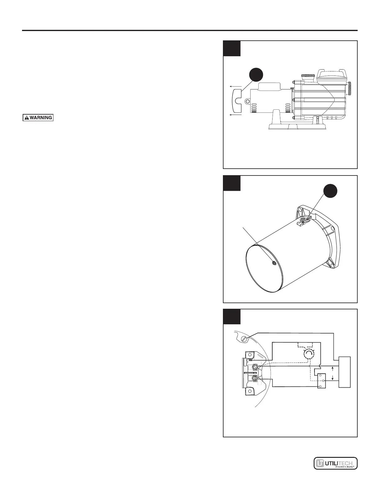
Electrical Code (NEC) requirements. Using a at
bladed screwdriver, unscrew two screws to remove
Motor Canopy (A) and to gain access to green
grounding terminal and voltage settings. See Figure 4.
Permanently ground motor using green grounding
terminal. See Figure 5. Use size and type wire
required by code. Connect green grounding
terminal to electrical service ground.
Connect a No. 8 AWG (8.4 sq/mm) solid copper
bonding wire (not included) to the bonding lug (C)
provided on the motor housing and to all metal parts of
the swimming pool, spa, or hot tub and to all electrical
equipment, metal piping or conduit within 5 ft. (1.5 m)
of the inside walls of swimming pool, spa, or hot tub.
Motor Wiring (for Two-Speed)
Wire the pump motor as shown in Figure 6.
Be sure that the green ground wire is attached to
the designated ground terminal.
Run one hot lead from the circuit protector to
terminal L2. Run the other hot lead from the
circult protector to the common post of a Single
Pole Double throw (SPDT) switch. Run a wire
from one post of the the SPDT switch to Terminal
A (Low Speed). Run a wire from the other post
of the SPDT switch to terminal L1 (High Speed).
To connect a timer to the pump (optional – sold
separately), run one timer motor lead from the timer
motor to terminal L2 (common). Run the other timer
motor lead from the timer motor to the common
post of the SPDT switch.
NOTICE: Connect the timer so that it only interrupts
the Low Speed circuit.
A
C
Circuit
Protector
Minimum switch and timer amp rating must equal
Branch Fuse Rating given in "Recommended Fusing
and Wiring Data" table.
Back of motor with
Terminal Board
L2=COM
L1=HI
A=LOW
A
L2
L1
Low Speed
High Speed
Remote
SPDT
Switch
Ground (Green)
Common
If using a timer, connect it to interrupt low speed only.
Timer
(Optional)
230V
6