ENGLISH
- 32 -
6 - CONTROL PANEL
When power is on, the control unit checks that display correctly
operates by switching on all segments for 1.5 sec. 8.8.8.8.
Firmware version, e.g. Pr 2.4, will be viewed in the following
1.5 sec.
Panel will be viewed upon completion of this test.
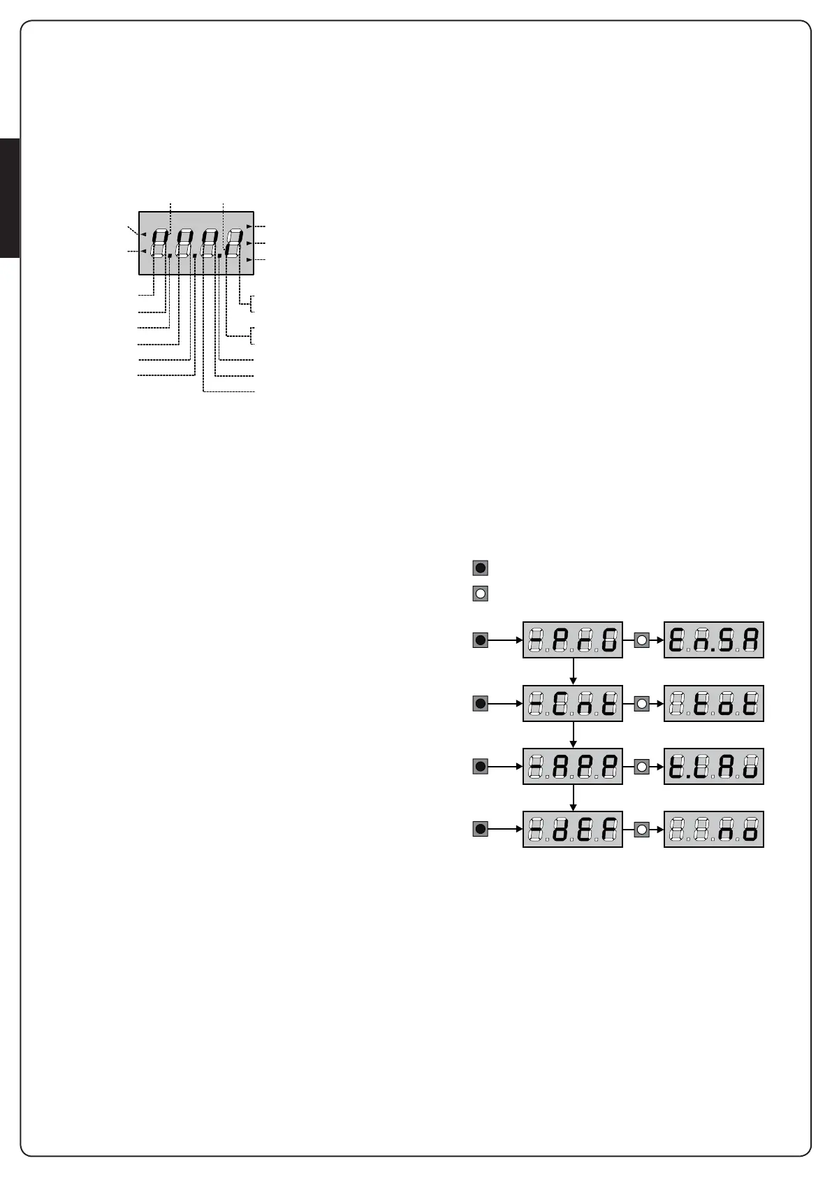
The control panel represents the physical status of the terminal
board contacts and of the program mode keys: if the upper
vertical segment is on, the contact is closed; if the lower vertical
segment is on, the contact is open (the above picture shows
an instance where the inputs LIMIT SWITCH, PHOTOCELL 1,
PHOTOCELL 2, SAFETY RIBBONS 1, SAFETY RIBBONS 2 and STOP
have all been correctly connected).
The segments indicated as REMOTE SAFETY show the status
of the remote safety devices for the device connected to the ADI
connector.
• If the ADI interface is not enabled (no device connected), both
segments remain turned off.
• If the device indicates a photocell alarm, the upper segment
comes on.
• If the device indicates an edge alarm, the lower segment comes
on.
• If the device indicates a stop alarm, both segments start
flashing.
Points being among display digits show the status of
programming push-buttons: as soon as a push-button is pressed,
its relevant point turns on.
The arrows on the left of the display show the state of the
start inputs. The arrows light when the related input is closed.
The arrows on the display right side show the gate status:
• The highest arrow turns on when the gate is into its opening
phase. If it blinks, it means that the opening has been caused
by a safety device (border or obstacle detector).
• The central arrow shows that the gate is on pause.
If it blinks, it means that the time countdown for the automatic
closing has been activated.
• The lowest arrow blinks when the gate is into its closing phase.
If it blinks, it means that the closing has been caused by a
safety device (border or obstacle detector).
6.1 - USE OF THE DOWN, MENU AND
UP KEYS FOR PROGRAMMING
Programming of the functions and times of the controller is
performed using a special configuration menu that is accessed
and explored using 3 keys, DOWN, MENU, and UP, which are
located below the display.
m CAUTION: Except in the configuration menu, pressing
the UP key activates a START command and pressing the
DOWN key activates a START PEDESTRIAN command.
To activate the programming modes (the display must show the
control panel), press and hold down the MENU key until -PrG
appears on the display.
Hold down the MENU key to scroll through the 4 main menus:
-PrG CONTROLLER PROGRAMMING
-Cnt COUNTERS
-APP SELF-LEARNING OF WORKING TIMES
-dEF LOAD DEFAULT PARAMETERS
To enter one of the four main menus, just release the MENU key
when the menu you want appears on the display.
To move through the four main menus, press the UP and DOWN
keys to scroll through the various items. Press the MENU key to
display the current value of the selected item and change it if
needed.
OPENING IN PROGRESS
OPEN CONTACTCLOSED CONTACT
START
PEDESTRIAN
START
PAUSE (GATE OPENED)
CLOSING IN PROGRESS
STOP
PHOTOCELL 1
DOWN
PHOTOCELL 2
SAFETY RIBBON 1
MENU
LIMIT SWITCH (MOTOR 2)
ENCODER (MOTOR 1)
LIMIT SWITCH (MOTOR 1)
ENCODER (MOTOR 2)
UP
REMOTE SAFETY
SAFETY RIBBON 2
MENU
3”
3”
3”
3”
MENU
6”
MENU
9”
MENU
12”
KEY PRESSED
KEY RELEASED