ENGLISH
- 25 -
4 - DESCRIPTION OF THE CONTROL
UNIT
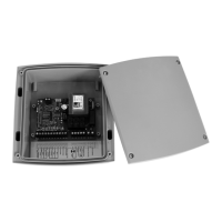
The digital control unit CITY2+ is an innovative V2 product that
guarantees a safe and reliable automation of leaf swing or sliding
gates.
CITY2+ is provided with a display that, not only makes
programming simple, but also allows a continuous monitoring of
the input statuses; in addition, thanks to a menu structure, the
working schedule and the operation logic can be set easily.
In compliance with the European standards concerning electrical
safety and electromagnetic compatibility (EN 60335-1,
EN 50081-1 and EN 50082-1) it has been equipped with the low
voltage circuit total electric insulation (motors included) from the
network voltage.
Other characteristics:
• Power supply protected from short circuits within the controller,
on the motors and on the connected accessories
• Adjustment of the power by partializing the current
• Detecting obstacles by monitoring the current on the motors
(current sensing probe)
• Automatic learning of the operation time.
• Tests for safety devices (photocells, safety ribbons and mosfet)
before each opening.
• Deactivation of safety inputs through the configuration menu:
no jumper is required for terminals concerning safety devices
that have not been installed, yet. You will only need to disable
this function from its relevant menu.
• The device can operate without mains power, by using the
optional battery pack (code 161212).
• Low voltage output that can be used for a signal light or a
24 V flashing light.
• Auxiliary relay with programmable logic for courtesy light,
flashing light or other use.
• ENERGY SAVING FUNCTION
5 - INSTALLATION
Installation of control unit and safety devices must be carried out
with power disconnected.
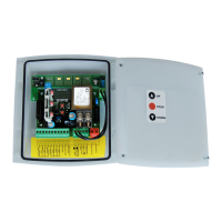
5.1 - POWER SUPPLY
Models CITY2+ / CITY2+L
The control unit must be fed by a 230V 50Hz (120V - 50/60Hz
for the 120V models) electric line, protected by a differential
magnetothermal switch complying with the law provisions in
force.
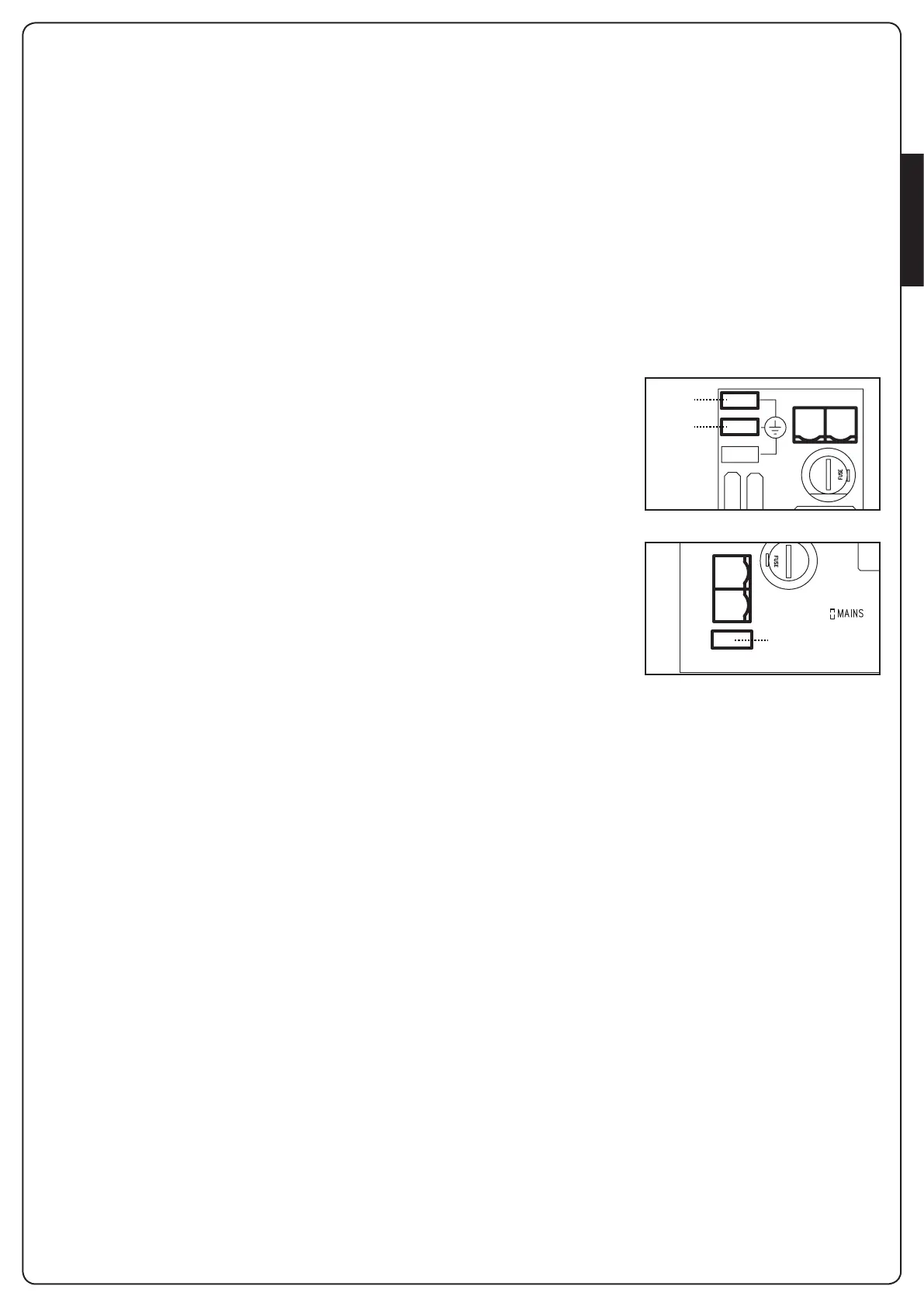
Connect phase and neutral to terminals L and N of the board
located next to the transformer.
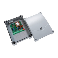
CITY2+
Connect the earth cable
of the system to the preset
faston A
Connect the earth cable
of the motor to the preset
faston B
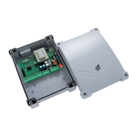
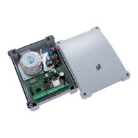
CITY2+L
Connect the ground cable
of the system and of
motors to faston A
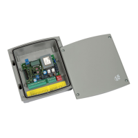
Model CITY2+BC
Connect the + pole of the ECO LOGIC battery box to the BAT+
terminal on the control unit (use a faston for the connection)
Connect the - pole of the ECO LOGIC battery box to the BAT-
terminal on the control unit (use a faston for the connection)
5.2 - MOTORS
CITY2+ control unit can control one or two 24V motors.
If the control unit needs to control one motor only, the latter must
be connected to terminals of motor 1.
Connect motor 1 cables as follows:
• opening cable to terminal Z3
• closing cable to terminal Z4
Connect motor 2 (if any) cables as follows:
• opening cable to terminal Z5
• closing cable to terminal Z6
m PLEASE NOTE: to avoid interference between the
motor and the photocells, it is essential to connect both the
motor casing and the control unit frame to the electrical
system ground.
F1
LN
A
B
LN
A