ENGLISH
- 10 -
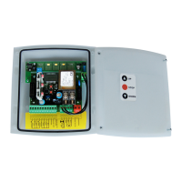
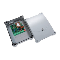
DESCRIPTION OF THE CONTROL UNIT
TheFLEXY2controlunitisaninnovativeV2productguaranteeing
safetyandreliabilityforswinggateautomation.
TheFLEXY2designhasbeenaimedatcreatingaproductwhich
adaptstosuitallneeds,thusobtaininganextremelyversatile
controlunitsatisfyingallthenecessaryrequirementsfora
functionalandefcientinstallation.
• 230V-50Hzor120V-60Hzpowersupplies,dependingonthe
model,for2singlephasemotors(700Wglobal).
• Inputforkeyswitchorpush-button.
• Inputforsafetyphotocell.
• Inputforsafetyedge,capableofhandlingstandardedges
withswitchnormallyclosedandconductiverubberedgeswith
nominalresistanceof8.2kOhms.
• Inputsforopenandcloselimitswitches
• Pre-openingsafetydevicetesting.
• Dip-switchprogrammableoperationallogic.
• Adjustmentofmotorpowerandoperationtimebymeansofa
trimmer.
• Fitted433.92MHzradioreceiver
• Possibilityofsaving240PersonalPasstransmitters
(433.92MHz)
• LEDmonitoringofinputs.
• Courtesylightoutput.
• RJ45connectortoconnectthecontrolunittotheprogrammer
PROG2viastandardnetworkcable(UTP)
• IP55casing.
INSTALLATION
Installationofthecontrolunit,thesafetydevicesandaccessories
mustbeperformedwiththepowersupplydisconnected.
POWER SUPPLY
Thecontrolunitmustbepoweredbymeansofa230V-50Hz
or120V-60Hzpowerline,dependingonthemodel,protected
byadifferentialmagnetothermalswitchincompliancewithlegal
regulations.
ConnectthepowercablestothecontrolunitL and N terminals.
MOTORS
ThecontrolunitcancontroloneortwoasynchronousACmotors.
Ifthecontrolunitisusedtocontrolonlyonemotor,thenthis
mustbeconnectedtotheterminalsrelatingtomotor1.
Connectthecablesformotor1asfollows:
• OpeningcabletoterminalK3
• ClosingcabletoterminalK5
• CommonreturncabletoterminalK4
• Start-upcapacitorbetweenterminalsK3 and K5
Connectthecablesformotor2(ifpresent)asfollows:
• OpeningcabletoterminalK6
• ClosingcabletoterminalK8
• CommonreturncabletoterminalK7
• Start-upcapacitorbetweenterminalsK6 and K8
PHOTOCELLS
Thecontrolunithasa24VACpowersupplyforphotocellswith
switchnormallyclosed,andcanperformanoperationaltest
beforetostartingthegateopeningprocedure.
Thephotocellcanbeusedwithtwosettings:
1. Photocell always active:
Interventionofthephotocellduringopeningorclosingcauses
thegatetostop.Whenthephotocellrestores,thegatere-
opens completely.
2. Photocell NOT active during opening:
Interventionofthephotocellduringopeningisignored.
Interventionofthephotocellduringclosingcausesthegateto
re-open completely.
Independentlyofthesettingselected,whenthegateispaused
whileopening,thetimecountforanyautomaticre-closurewill
onlystartafterthephotocellrestores.
• Connectthephotocelltransmitterpowercablesbetween
terminals L10 (GND)andL11 (+)onthecontrolunit.
• Connectthephotocellreceiverpowercablesbetweenterminals
L10 (GND)andL9 (+)onthecontrolunit.
• ConnectthephotocellreceiveroutputbetweenterminalsL4
and L8 on the control unit.
SAFETY EDGES
Thecontrolunithasaninputforcontrollingsafetyedges;this
inputiscapableofcontrollingstandardedgeswithswitch
normallyclosedandconductiverubberedgeswithnominal
resistanceof8.2kOhms.
Edgescanbeusedwithtwosettings:
1. Edge always active:
Interventionoftheedgeduringopeningorclosingcauses
inversionofthedirectionofmovementinordertofreethe
bodythatcausedtheedgetointervene.Thegatestopsafter
approx. 3 seconds.
2. Edge NOT active during opening:
Interventionoftheedgeduringopeningisignored.
Interventionoftheedgeduringclosingcausesthegateto
re-open completely.
Independentlyofthesettingsselected,anysubsequentautomatic
re-closurewillbecancelled.
Standard edge with switch normally closed: connecttheedge
cablesbetweenterminalsL5 and L8 on the control unit.
InordertosatisfytherequirementsofstandardEN12978,it
isnecessarytoinstallsafetyedgeswithacontrolunitwhich
constantlymonitorscorrectoperation.Ifcontrolunitsareused
withtheoptionofrunningtestsbymeansofinterruptingthe
powersupply,connectthecontrolunitpowersupplycables
betweenterminalsL10(GND)andL11(+).
Conductive rubber edge:connecttheedgecablesbetween
terminalsL5andL8onthecontrolunit.
m PLEASE NOTE: operational testing on edges is
reserved for standard edges (only if equipped with suitable
control units).
DO NOT enable testing if conductive rubber edges are used
or standard edges used without a suitable control unit for
controlling function.

 Loading...