26 • vacon modbus
Tel.+358 (0)201 2121 • Fax +358 (0)201 212 205
6
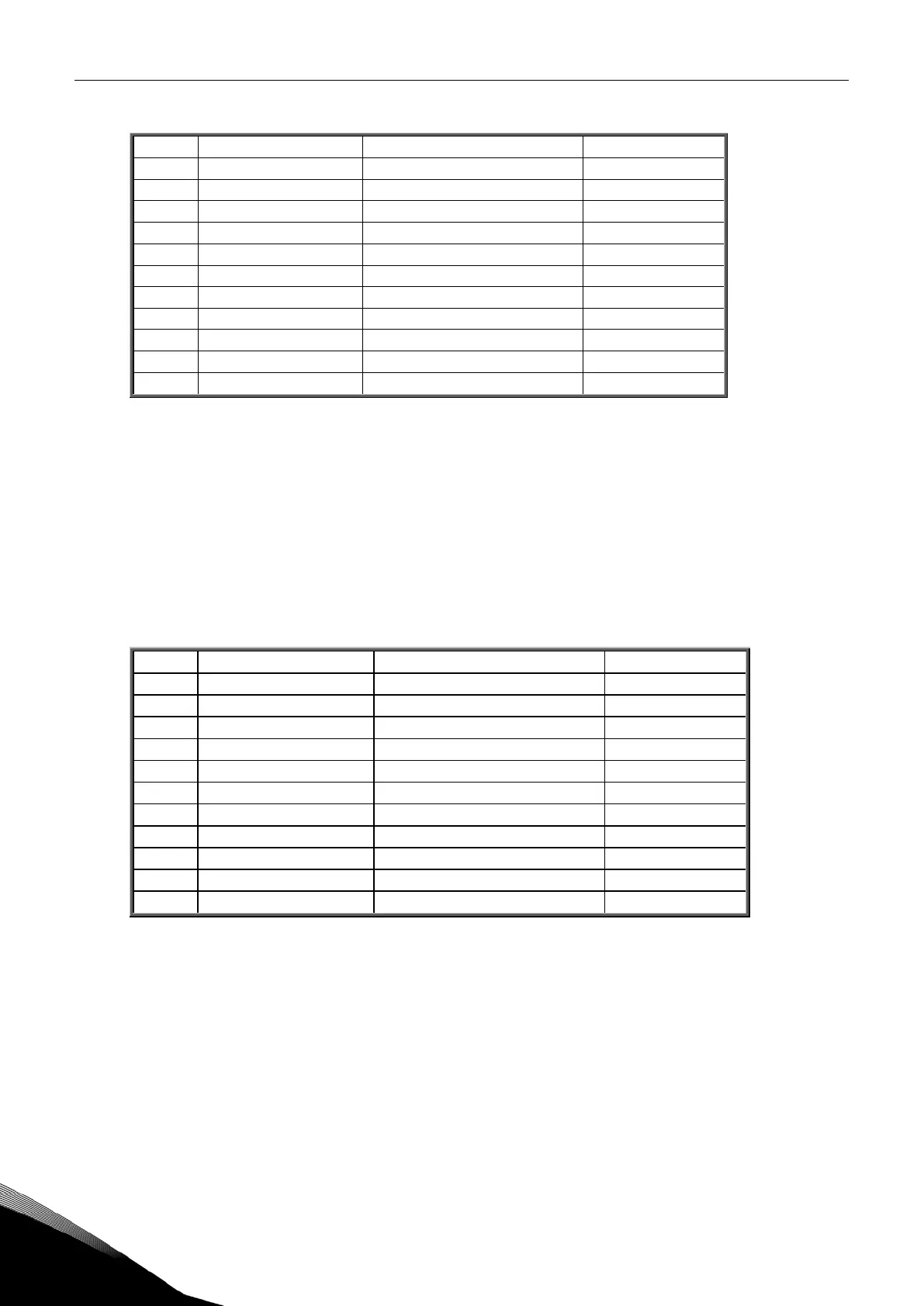
Process Data Master -> Slave (max 22 bytes)
2001 32001, 42001 FB Control Word Binary coded
2002 32002, 42002 FB General Control Word Binary coded
2003 32003, 42003 FB Speed Reference 0…10000 %
2004 32004, 42004 FB Process Data In 1 Integer 16
2005 32005, 42005 FB Process Data In 2 Integer 16
2006 32006, 42006 FB Process Data In 3 Integer 16
2008 32008, 42008 FB Process Data In 5 Integer 16
2009 32009, 42009 FB Process Data In 6 Integer 16
2010 32010, 42010 FB Process Data In 7 Integer 16
2011 32011, 42011 FB Process Data In 8 Integer 16
Table 11.
The use of process data depends on the application. In a typical situation, the device is started and
stopped with the ControlWord (CW) written by the Master and the Rotating speed is set with Refer-
ence (REF). With PD1…PD8 the device can be given other reference values (e.g. Torque reference).
With the StatusWord (SW) read by the Master, the status of the device can be seen. Actual Value (ACT)
and PD1…PD8 show the other actual values.
6.2.3
Process data in
This register range is reserved for the control of the frequency converter.
Process data in
is located in
range ID 2001…2099. The registers are updated every 10 ms. See Table 12.
2001 32001, 42001 FB Control Word Binary coded
2002 32002, 42002 FB General Control Word Binary coded
2003 32003, 42003 FB Speed Reference 0…10000 %
2004 32004, 42004 FB Process Data In 1 Integer 16
2005 32005, 42005 FB Process Data In 2 Integer 16
2006 32006, 42006 FB Process Data In 3 Integer 16
2007 32007, 42007 FB Process Data In 4 Integer 16
2008 32008, 42008 FB Process Data In 5 Integer 16
2009 32009, 42009 FB Process Data In 6 Integer 16
2010 32010, 42010 FB Process Data In 7 Integer 16
2011 32011, 42011 FB Process Data In 8 Integer 16
Table 12. Fieldbus basic input table