modbus vacon • 27
24-hour support +358 (0)40 8371 150 • Email: vacon@vacon.com
6.2.3.1
Control word
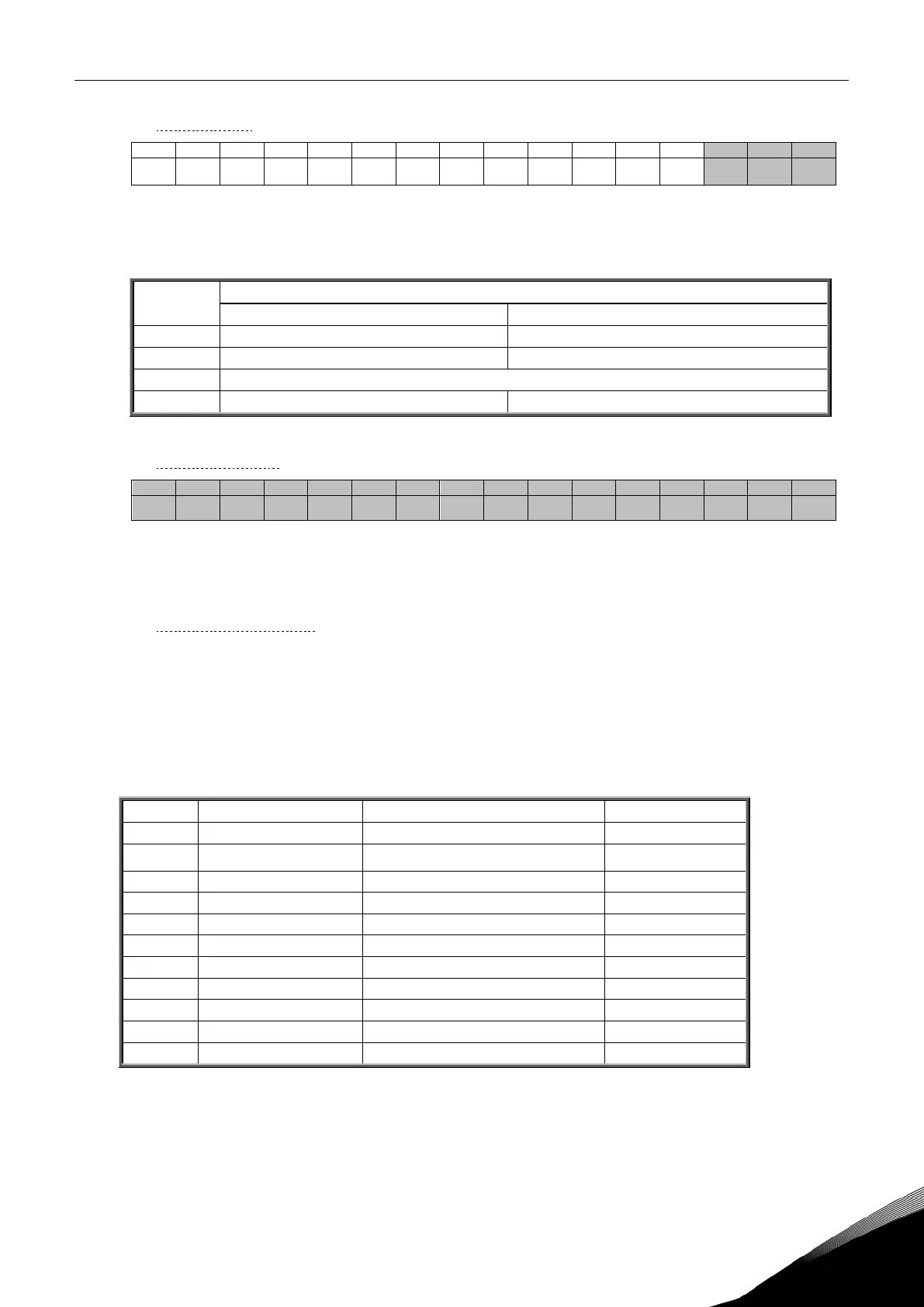
15 14 13 12 11 10 9 8 7 6 5 4 3 2 1 0
- - - - - - - - - - - - - RST DIR RUN
In Vacon applications, the three first bits of the control word are used to control the frequency con-
verter. However, you can customise the content of the control word for your own applications because
the control word is sent to the frequency converter as such.
Value = 0 Value = 1
0 Stop Run
1 Clockwise Counterclockwise
Rising edge of this bit will reset active fault
3….15 Not in use Not in use
Table 13. Control word bit descriptions
6.2.3.2
Speed reference
15 14 13 12 11 10 9 8 7 6 5 4 3 2 1 0
MSB LSB
This is the Reference 1 to the frequency converter. Used normally as Speed reference.
The allowed scaling is –10000...10000. In the application, the value is scaled in percentage of the fre-
quency area between the set minimum and maximum frequencies.
6.2.3.3
Process data in 1 to 8
Process Data In values 1 to 8 can be used in applications for various purposes. Update rate is 10 ms
for all values. See Vacon NX Application Manual for usage of these data values.
6.2.4
Process data out
This register range is normally used to fast monitoring of the frequency converter.
Process data out
is
located in range ID 2101…2199. See Table 14.
2101 32101, 42101 FB Status Word Binary coded
2102 32102, 42102 FB General Status Word Binary coded
2103 32103, 42103 FB Actual Speed 0…10000 %
2104 32104, 42104 FB Process Data Out1 See appendix 1
2105 32105, 42105 FB Process Data Out2 See appendix 1
2106 32106, 42106 FB Process Data Out3 See appendix 1
2107 32107, 42107 FB Process Data Out4 See appendix 1
2108 32108, 42108 FB Process Data Out5 See appendix 1
2109 32109, 42109 FB Process Data Out6 See appendix 1
2110 32110, 42110 FB Process Data Out7 See appendix 1
2111 32111, 42111 FB Process Data Out8 See appendix 1
Table 14. Fieldbus basic output table