layout and connections vacon • 5
24-hour support +358 (0)40 8371 150 • Email: vacon@vacon.com
3. RS-485 FIELDBUS BOARD LAYOUT AND CONNECTIONS
Vacon RS-485 Fieldbus Board is connected to the fieldbus through either a 5-pin pluggable bus con-
nector (board OPTC2) or a 9-pin female sub-D-connector (board OPTC8).
The communication with the control board of the frequency converter takes place through the stan-
dard Vacon Interface Board Connector.
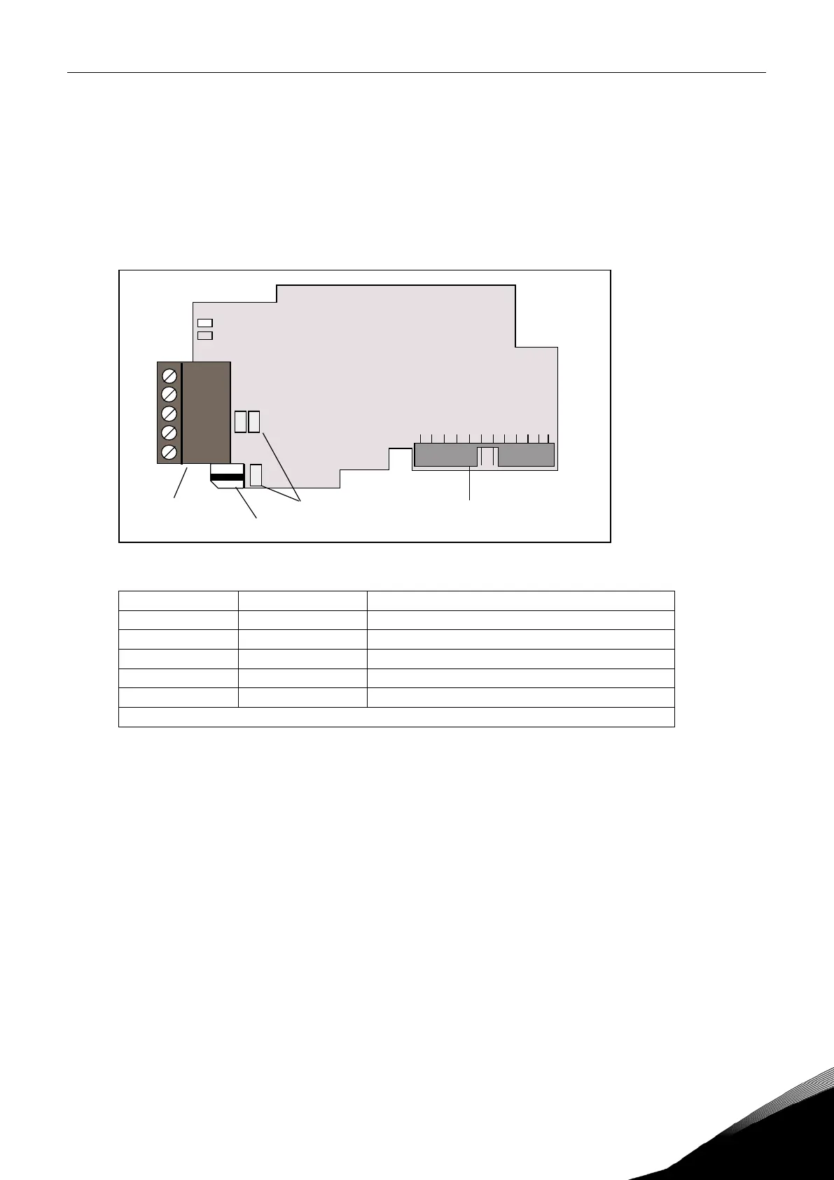
3.1 RS-485 OPTC2 option board
Figure 1. Vacon RS-485 option board OPTC2
NC* 1* No connection
VP 2 Supply voltage – plus (5V)
RxD/TxD –N 3 Receive/Transmit data – A
RxD/TxD –P 4 Receive/Transmit data – B
DGND 5 Data ground (reference potential for VP)
*You can use this pin (1) to bypass the cable shield to the next slave
Table 2. OPTC2 bus connector signals
X4
X1
Bus connector
Jumpers Interface board connector
Grounding plate
1
2
3
4
5