page 22 of 27
Documents are only to be used and distributed completely and unchanged. It is strictly the users´ responsibility to check carefully
the validity of this document with respect to his product. 25/11/2013 // 999281
+ Position any washers that are present between diaphragm
support disc and connection rod.
➨ Screw diaphragm clamping disc, diaphragm, diaphragm
support disc, and washers to connecting rod.
➨ Bring the diaphragm into a position in which it is in con-
tact with the housing and centered with respect to the bore
so that it will become clamped uniformly between housing
and head cover.
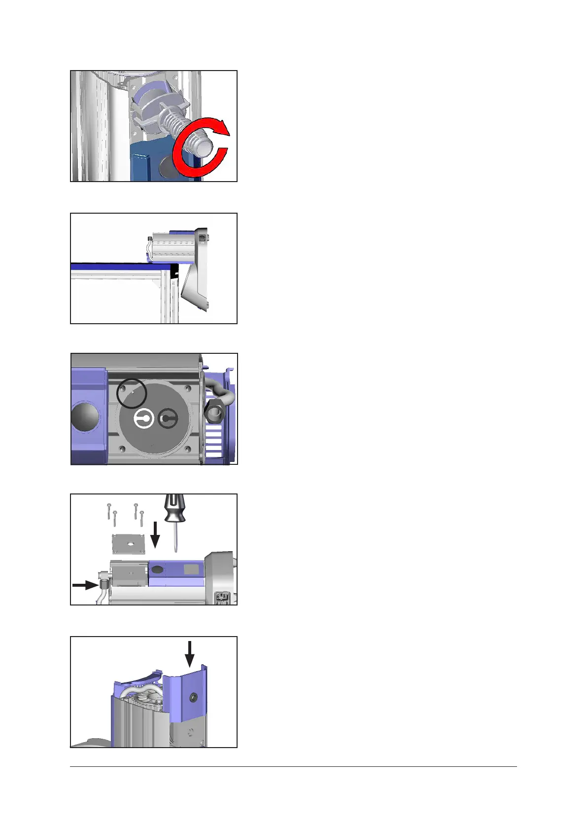
➨ Assemble head cover and valves.
+ Pay attention to the correct position of the guidance pin in
theheadcover(circleingure)!
+ Pay attention to correct orientation of the valves(see
gure):
Inlet sideofpumphead(blackvalve):Thevalvetongue
pointsatthekidney-shapedoriceinthevalveseat.
Outlet sideofpumphead(whitevalve):Thevalveisori-
ented the opposite direction as the valve at the inlet side.
Roundoriceunderthevalvetongue.
➨ LaydowntheBVConthesideofthepump,e.g.,atthe
edge of a workbench; support if necessary.
➨ Put on housing cover and housing cover insert.
+ Movehousingcoverinsertslightlytoensurethatthehead
covers are correctly positioned.
➨ Pay attention to washers and position screws. Screw in
4 screws with washers at the housing cover diagonally,
looselyatrstwithaTorxdriverT20,thentighten.
+ Do not tighten until head cover is in contact with housing,
maximumtorque:2.2ft
.
lb
f
(3Nm).
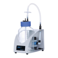
➨ Positionhosetoelbowttingandscrewontheunionnut.
➨ PositionBVCupright.
➨ Assemble the cover so that the groove in the in the face
side of the cover is at the inlet of the pump.
 Loading...