3Installation Manual auroMATIC 560
4 Installation
4.1 Scope of delivery
Using Table 4.1, verify the scope of delivery for the con-
troller set.
Item Quantity Components
1 1 auroMATIC 560 controller
2 1 VR 11 collector sensor
3 2 VR 10 standard sensor
4 1 C1/C2 cable
Table 4.1 Scope of delivery
4.2 Installing VR 10 standard sensor
The VR 10 standard sensor is designed so that it can be
used as an immersion sensor or flow sensor.
When used as a flow sensor, the sensor is secured to the
forward flow pipe or the return pipe using the supplied
tension band. In order to guarantee good heat transfer,
the sensor is flat on one side. We also recommend that
the pipe with the sensor is insulated, in order to enable
the best possible measuring of temperature.
Fig. 4.1 VR 10 standard sensor
4.3 Accessories
The following accessories are necessary in order to con-
nect a second collector array or an additional solar cyl-
inder to the controller, and to enable measurement of
the solar yield.
4.3.1 VR 10 standard sensor
The use of additional standard sensors is necessary if
you want to connect a second solar cylinder to the con-
troller.
An additional standard sensor is also required in order
to enable the measuring of yield.
4.3.2 VR 11 collector sensor
If a second collector array is connected, it is necessary
to install a second collector sensor from the Vaillant
accessory range.
4.4 Installing the controller housing
The controller is designed to be mounted on a wall, and
it is equipped with System ProE terminal strips. These
terminals must be used for all connections made at the
installation site.
Fig. 4.2 Opening the controller housing
The cover consists of two parts, which can be removed
separately.
• As shown in Fig. 4.2, pull the lower front cover off of
the controller housing.
C1/C2
C1 C2
KOL1
21
SP1
21
SP2
21
SP3
21
Ertrag
21
KOL2
21
230 V~
PE N L
KOL1-P
PE N L
LEG/BYP
PE N L
LP/UV1
PE N L
EP
21
KOL2-P/Z P
PE N L
12
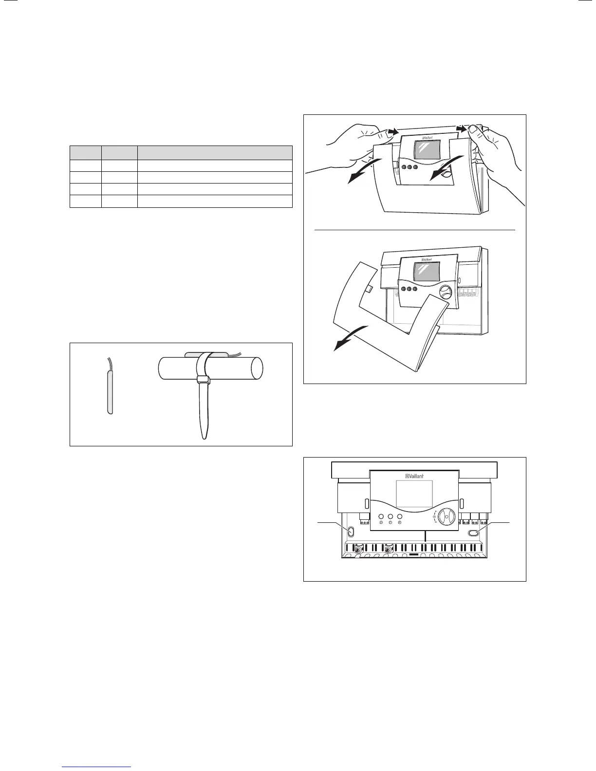
Fig. 4.3 Fastening the controller housing
• Mark the position of both holes (1 und 2) and drill the
bore holes.
• Select the wall plugs to suit the state of the wall, and
screw the controller housing on tightly.
Installation 4