14 Installation Manual auroMATIC 560
5.4 Hydraulic plan 3
Kol 1
230 V
Kol1-P
Gain
Sp1
Sp2
EP
S
1
2
KW
LegP
Kol2P
Kol2
HZ-K
HZ-K
HZ-K
C1 C2
C1 C2
C1 C2
230 V
I
II III
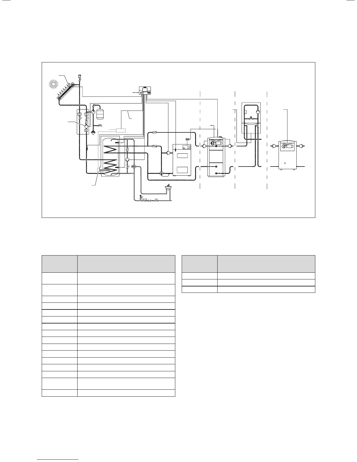
Fig. 5.9 Hydraulic plan 3 with system configuration: One col-
lector array, one solid-fuel boiler, one solar cylinder,
connection option for various heaters for reheating the
cylinder
Designation in
hydraulic plan/
wiring diagram
Components
I, II, III Connection option for various heaters for
reheating the cylinder
C1/C2 Connections for controlling the heater used for
reheating the cylinder
HZ-K Heating circuit(s)
KW Cold water
EP Electric heating rod (optional)
Kol1-P Solar circuit pump 1
Kol 1 Collector sensor 1
Kol2-P Reheating pump 2
Kol 2 Reheating sensor 2
Ertrag Gain
LegP Anti-Legionnaire’s pump
Sp1 Cylinder sensor 1
Sp2 Cylinder sensor 2
S Contactor
1 Option: Control contactor for optional electric
heating rod
2 400 V connection, 3 phase
Designation in
hydraulic plan/
wiring diagram
Components
230 V 230 V main power connection
F1 (T4) Fuse holder
VU / VK Heater wiring area
Table 5.6 Key for Fig. 5.9 and Fig. 5.10
5 Electrical installation