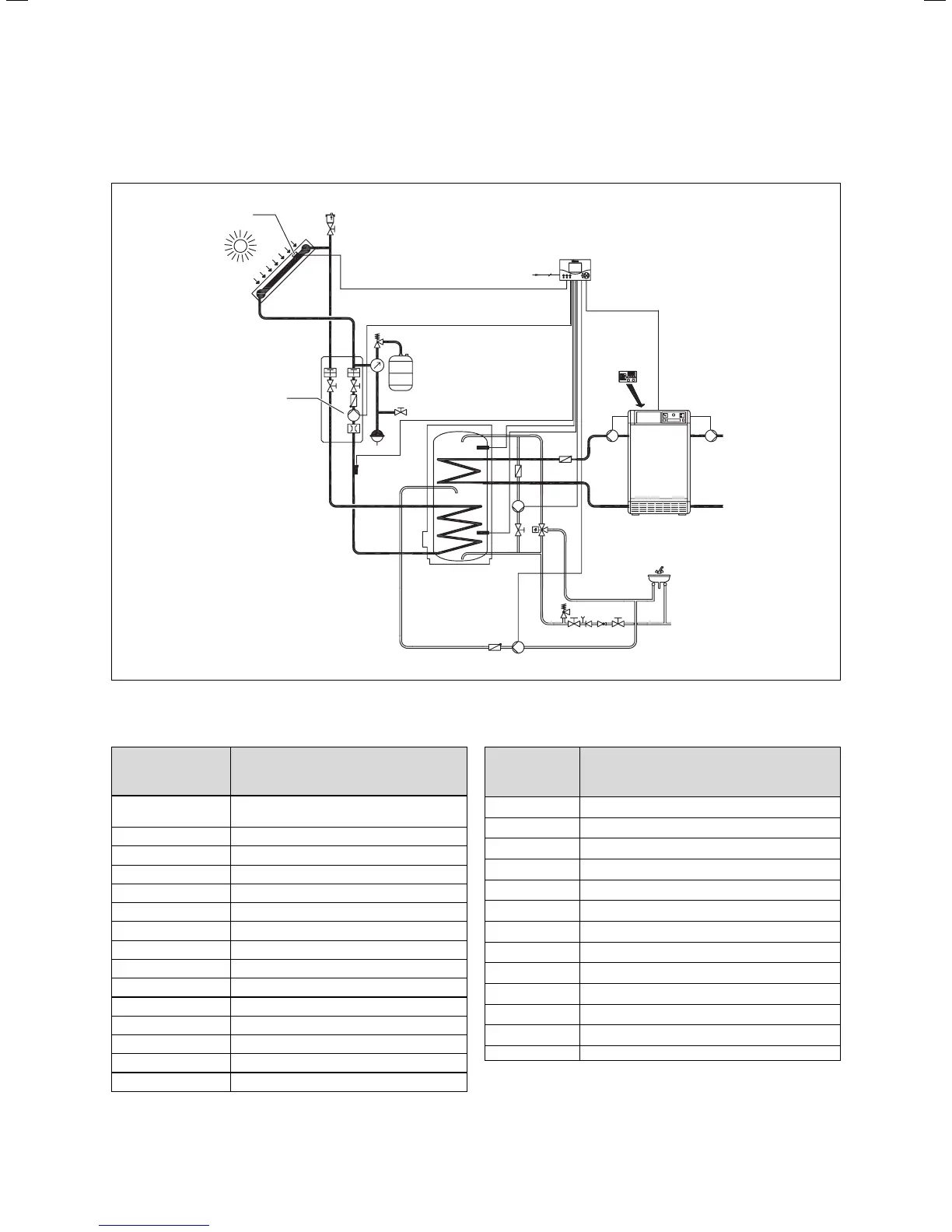
18 Installation Manual auroMATIC 560
5.5 Special plan: Heater with “hot water capable”
heating controller
230 V
VRC-MF/
VRC-UBW
SpF-E
HZ-K
KW
ZP
LegP
Sp1
Sp2
Gain
Kol1-P
Kol 1
Fig. 5.13 Connecting older boilers with “hot water capable”
heating controllers, e.g., VRC-MF
Designation in
hydraulic plan/
wiring diagram
Components
VRC-MF/VRC-UBW VRC-MF or VRC-UBW (heating controller in
the boiler)
SpF-E Heating controller cylinder sensor entrance
HZ-K Heating circuit
KW Cold water
ZP Circulation pump
Kol1-P Solar circuit pump 1
Kol 1 Collector sensor 1
Ertrag Gain
LegP Anti-Legionnaire’s pump
Sp1 Cylinder sensor 1
Sp2 Cylinder sensor 2
230 V 230 V main power connection
VK / VRC Boiler with VRC-UBW or VRC-MF
KF Boiler sensor 1
Bus / FBG Connection for remote-control device
Designation in
hydraulic plan/
wiring diagram
Components
SpF Cylinder sensor
DCF / AF DCF external sensor
ext. St. External error message
1. St. External control level 1
2. St. External control level 2
GW Gas pressure monitor
AK Flue gas flap
WM Water shortage protection
ext. M External solenoid valve
UV / LP Switching valve / filling pump
HP B-circuit heating pump
230 V~ Fuses
F 1, F 2 Fuses
Table 5.8 Key for Fig. 5.13 and Fig. 5.14
5 Electrical installation