16 Installation Manual auroMATIC 560
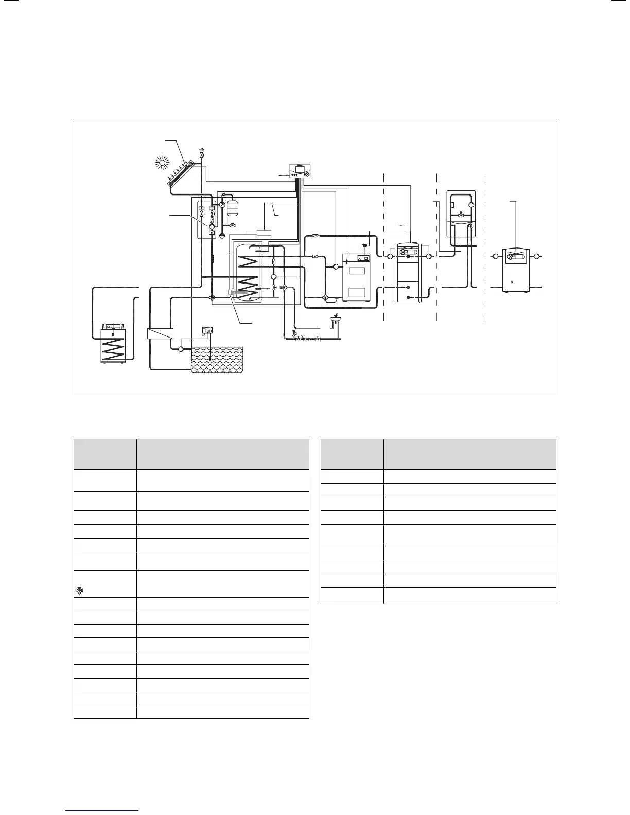
Hydraulic plan 3: Connection of a second cylinder or
swimming pool
Kol1-P
Kol 1
Sp2
Sp1
S
2
1
LP / UV 1
KW
LegP
SR
Sp3
Sp3
230 V
C1 C2
EP
Gain
A
C1 C2
C1 C2
HZ-K
HZ-K
HZ-K
230 V
Kol2
Kol2-P
I
II
III
Fig. 5.11 Hydraulic plan 3: Connection of a second cylinder or
swimming pool
Designation in
hydraulic plan/
wiring diagram
Components
I, II, III Connection option for various heaters for
reheating the cylinder
C1/C2 Connections for controlling the heater used for
reheating the cylinder
HZ-K Heating circuit
KW Cold water
EP Electric heating rod (optional)
SR Swimming pool controller (provided by cus-
tomer)
LP / UV 1
Switching valve
UV 1 in current-free state
A Alternative
Kol1-P Solar circuit pump 1
Kol 1 Collector sensor 1
Kol2-P Reheating pump 2
Kol 1 Collector sensor 1
Kol 2 Reheating sensor 2
Ertrag Gain
LegP Anti-Legionnaire’s pump
Sp1 Cylinder sensor 1
Designation in
hydraulic plan/
wiring diagram
Components
Sp2 Cylinder sensor 2
Sp3 Cylinder sensor 3
S Contactor
230 V 230 V main power connection
1 Option: Control contactor for optional electric
heating rod
2 400 V connection, 3 phase
230 V 230 V main power connection
F1 (T4) Fuse holder
VU / VK Heater wiring area
Table 5.7 Key for Fig. 5.11 and Fig. 5.12
5 Electrical installation