Supplied By www.heating spares.co Tel. 0161 620 6677
39Instructions for installation and servicing ecoTEC
7.2 Servicing the burner module
7.2.1 Removing the burner module
The burner module consists of the burner, fan, gas valve
und the gas supply (mixer tube). These four components
make up the complete assembly, the burner module.
Danger!
There is danger of being injured or burnt by the
burner module and at all components carrying
water. Only carry out work on these compo-
nents once they have cooled down.
Proceed as follows to remove it:
• Turn off the boiler
• Isolate the electrical supply to the boiler.
• Remove boiler bottom cover by releasing the two
spring retaining lugs and lowering the rear of the bot-
tom cover.
• Gently pull the bottom cover backwards to remove
from the appliance.
• Turn off the gas service valve.
• Turn off the boiler CH service valves.
• Loosen screw, release the front case spring retaining
clips located beneath the front edge of the appliance.
• Remove the front casing by easing forward the bottom
edge and gently lifting.
• Lower electronic control box.
2
3
1
Fig. 7.1 Dismantling air intake pipe
• Remove screw (2) and remove the air intake pipe (1).
• Disconnect the gas supply (3) on the gas valve. Ensure
the corrugated gas pipe does not twist by holding the
flattened section of the pipe, with an open ended
spanner, whilst loosening the union nut.
Caution!
Damage to corrugated gas pipe!
Under no circumstances must the burner mod-
ule be suspended from the flexible corrugated
gas pipe.
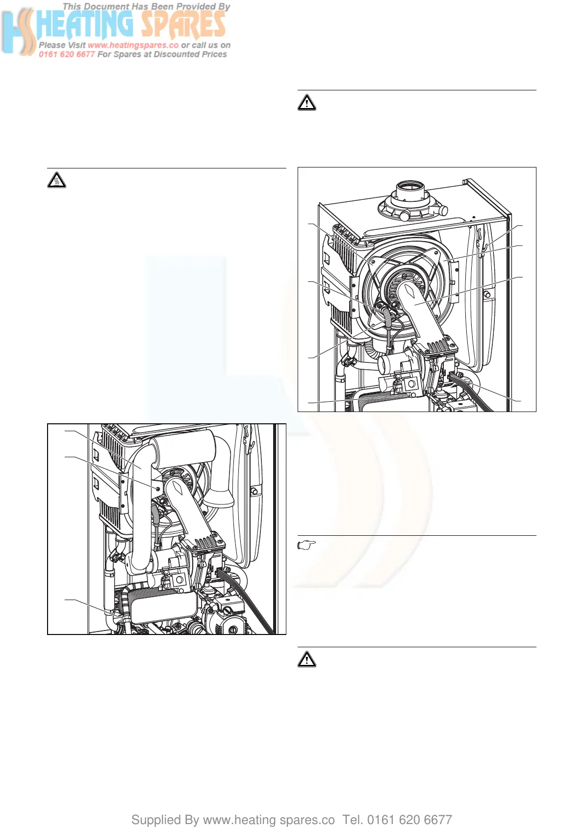
10
11
9
8
4
5
6
7
Fig. 7.2 Dismantling burner module
• Disconnect HT lead (5) and earth lead (6) from spark
electrode.
• Remove four nuts (4) from burner manifold.
• Disconnect two electrical connections (7 and 8) from
fan and gas valve.
• Pull forward and remove burner, gas valve and fan
assembly (9) from integral condensation heat
exchanger (10).
Note
You can suspend the burner module on the hook
(11) while carrying out maintenance tasks.
• After removing the thermal compact module, clean
the components as described below.
7.2.2 Cleaning the integral condensation heat
exchanger
Caution!
Protect the electronics box against sprayed
water.
Inspection and maintenance 7