Supplied By www.heating spares.co Tel. 0161 620 6677
51Instructions for installation and servicing ecoTEC
3
2
1
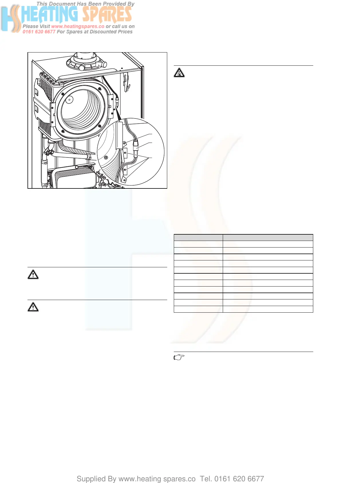
Fig. 9.6 Primary heat exchanger holder
• Disconnect the plug-in connection (2) of the thermal
fuse in the primary heat exchanger.
• Remove the three screws (3) on the primary heat
exchanger holder.
• Turn the holder to the side around the rivet (1), pull
the primary heat exchanger downwards to the right
and remove it from the appliance.
• Mount the new primary heat exchanger in reverse
order and replace the seals.
Caution!
Risk of damaging the primary heat exchanger!
Neither loosen nor retighten the four screws
(Fig. 9.5, Pos. 4).
Caution!
Insert the seal rings for the flow and return
pipe on the primary heat exchanger with a suit-
able lubricant.
Insert the flow and return connection in the pri-
mary heat exchanger as far as they will go and
make sure the clamps are fitted correctly on
the flow and return pipe (see fig. 9.5).
• Fill and vent the boiler as required.
• After completing the work, check for gas and water
leaks and perform a function check (see section 7.6)!
9.6 Replacing electronics and display
Danger!
Before replacing the component, comply with
the safety instructions in Section 9.1.
• Comply with the assembly and installation manuals
provided with the spare parts.
Replacing display or electronics
If you are replacing only one of the two components, the
parameter adjustment functions automatically. On turn-
ing on the appliance, the new component takes over the
previously set parameters from the components that are
not replaced.
Replacing display and electronics
When replacing both components, after being turned on,
the appliance goes to fault and displays the error mes-
sage “F70”.
• In the second diagnostic level, under the diagnostic
number “d.93” enter the number of appliance variant
according to Table 9.1 (see section 8.1.2).
The electronics is now set to the appliance type and the
parameters of all adjustable diagnostics numbers corre-
spond to the factory settings.
Appliance Device specific number
ecoTEC plus 612 0
ecoTEC plus 615 1
ecoTEC plus 618 2
ecoTEC plus 624 3
ecoTEC plus 630 4
ecoTEC plus 637 5
ecoTEC plus 824 6
ecoTEC plus 831 7
ecoTEC plus 837 8
ecoTEC pro 24 7
ecoTEC pro 28 0
Table 9.1 Device specific numbers
9.7 Check CO
2
content and if necessary set (air-
ratio adjustment)
Note
Checking/adjustment of this value is required in
the following instances: replacement of gas
valve, conversion to or from Natural Gas/LPG
or if incorrect combustion is suspected!
• Remove the front cover.
• Press the “+” and “-” keys simultaneously.
The “Full load mode” is activated.
• Wait at least 5 minutes until the appliance reaches its
operating temperature.
Parts replacement 9
 Loading...


