16 Installation and maintenance manual ecoTEC
3.11 Pump specifications
3.11.1 Circulating pump
only ecoTEC plus:
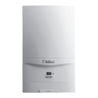
The circulating pump is included in the boiler. The resid-
ual pump discharge height depending on the overflow
valve is shown in Fig. 3.10.
The operating mode of the 2-step pump can be adjusted
below the diagnosis point d.12, see Section 8.1.2.
400
300
200
100
0
0 200 400 600 800 1000 1200 1600
Lift
[
mbar
]
Volumeflow
[
l/h
]
1800
1400
2. Step1. Step
Fig. 3.10 Pump specifications ecoTEC plus
only ecoTEC pro:
The circulating pump is included in the boiler. The eco-
TEC pro appliances are fitted with a single-stage pump.
The residual pump discharge height depending on the
overflow valve is shown in Fig. 3.11.
400
300
200
100
0
0 200 400 600 800 1000 1200 1600
Lift
[
mbar
]
Volumeflow
[
l/h
]
1800
1400
Fig. 3.11 Pump specifications ecoTEC pro
3.11.2 System bypass
An automatic system bypass is provided in the boiler.
The boiler is suitable for use in systems with thermostat-
ic radiator valves and no additional bypass is required.
The overflow valve is adjustable, see Section 5.8.
3.11.3 Venting
The boiler is fitted with an automatic air vent. Additional
provision should be made to enable the heating system
to be vented during filling and commissioning either by
automatic air vents or manually.
3.12 Condensate trap
The boiler is fitted with a siphon condensate discharge
(ecoTEC plus) or a condensate trap (ecoTEC pro) incor-
porating a water trap of 140 mm.
4 Boiler installation sequence
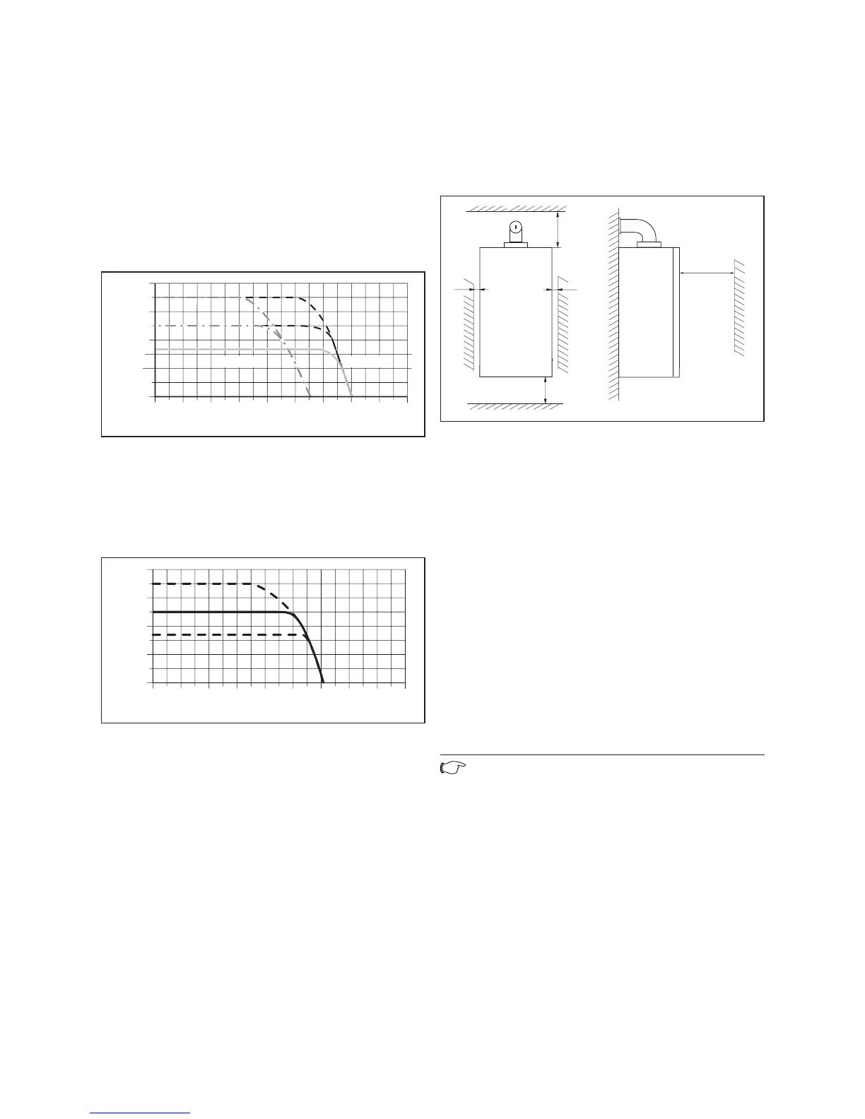
4.1 Required minimum distances/assembly clear-
ances
min
min 5
min 5
min 500**
min 180
167/246*
Fig. 4.1 Distances during installation (dimensions in mm)
Both for the installation/assembly of the appliance and
also for carrying out maintenance tasks later, you need
the minimum distances and minimum assembly clear-
ances given below:
– side distance: 5 mm on each side
– lower side 180 mm
– upper side*: 167 mm for flue system
Ø 60/100
246 mm for flue system
Ø 80/125 mm
– front side**: 500 mm
This distance is needed for easier
access during maintenance tasks.
It is not necessary to keep a clearance between the
appliance and combustible substances or components,
as at the rated heating power of the appliance, the tem-
perature here is always lower than the permitted tem-
perature of 85 °C.
Note
If the boiler is to be fitted in a timber framed
building, it should be fitted in accordance with
British Gas publication DM2 ‘Guide for gas
installations in timber framed housing’.
3 General requirements
4 Boiler installation sequence

 Loading...